czahlzq@163.com+86 151 3177 0577

Industrial Coupling

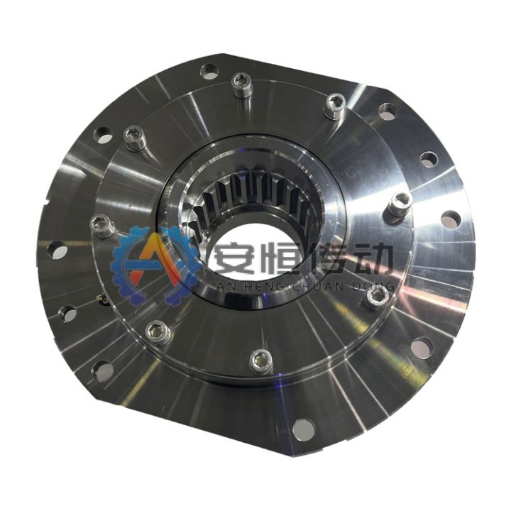
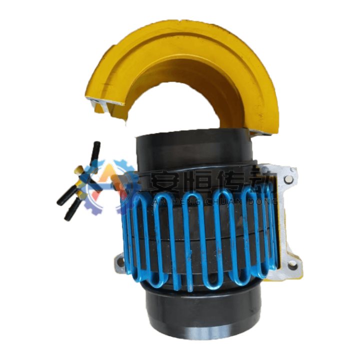
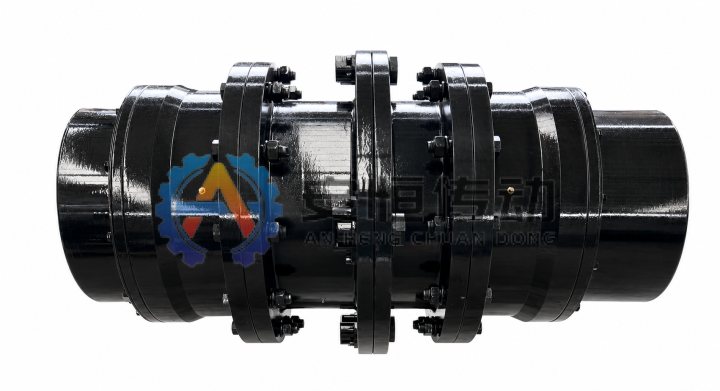
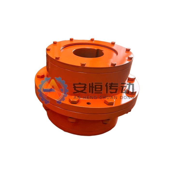
Drum Gear Coupling

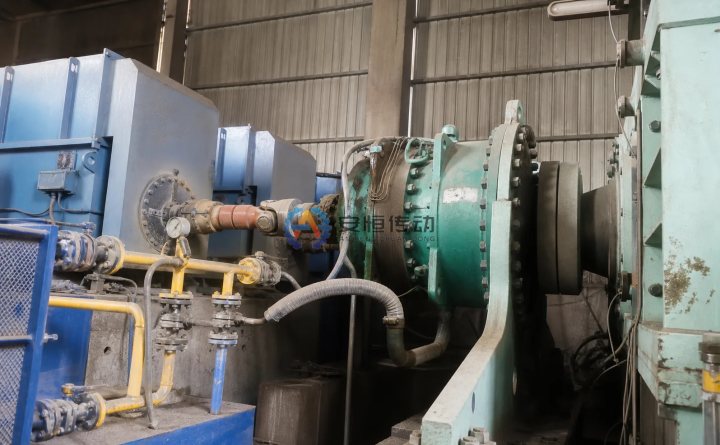
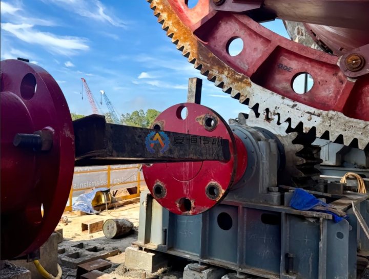
Designed for steel rolling mills, cranes, mining drives and port handling equipment; high torque capacity with axial, angular and radial misalignment compensation.

  • Metal gear meshing
  • High load capacity
  • Compensates axial, angular and radial offset
  • High rigidity
Series
GIICL / GIICLZ / WGP / WGT / NGCL / GICL
Model entries
132
HTML tables
6
Drawings / files
19

No drawing? Send old coupling photos, nameplate details and shaft dimensions.

Documented engineering data

Product Overview and Application Boundary

A drum gear coupling consists of two crowned external gear sleeves and a pair of straight internal gear rings. Torque is transmitted through internal and external gear meshing, while the crowned sleeve can swing inside the internal gear ring to compensate angular, axial and radial misalignment between shafts. The crowned tooth profile improves tooth contact, giving the coupling high torque capacity, large angular displacement, smooth transmission, high efficiency and long service life. It is widely used in metallurgical machinery, heavy machinery, mining equipment, cranes and conveying systems.

Typical use

Recommended for steel rolling mills, cranes, mining drives and port handling equipment.

Selection focus

Confirm torque, speed, shaft diameter, keyway, service factor, misalignment and working environment before selection.

Custom options

Bore, keyway, material, heat treatment, dynamic balancing, surface treatment and export packing can be customized.

Material and inspection

Common materials include 45 steel, 42CrMo or project-specified grades; inspection records can be supplied on request.

Manufacturing Control

Machining, Heat Treatment and Inspection Process for Drum Gear Coupling

This route follows Drum Gear Coupling from drawing and material review through blank preparation, CNC rough machining, feature machining, heat treatment, reinspection, finish machining, assembly and final release. The approved drawing determines the exact material and treatment route.

Manufacturing and inspection flowchart for Drum Gear Coupling
Typical machining and heat-treatment route for Drum Gear Coupling; drawing-specific operations are released only after technical approval.
  1. 01. Drive data and drawing review: Confirm torque, speed, shaft interfaces, alignment allowance, acceptance criteria and the approved drawing before release.
  2. 02. Material certificate and blank inspection: Verify material identity, certificate, heat number, blank dimensions and the specified forging, casting or bar-stock route.
  3. 03. Saw cutting and forging/casting blank preparation: Saw-cut the stock or prepare the forging/casting blank, remove scale, transfer traceability marks and retain machining allowance.
  4. 04. CNC rough turning of hubs and sleeves: Use CNC or vertical lathes to rough-turn faces, outside diameters, bores and datum shoulders, leaving allowance for heat-treatment distortion and finishing.
  5. 05. Hobbing/shaping crowned and mating gear teeth: Machine the named teeth, grooves, holes, splines or mechanism features by turning, milling, hobbing, shaping, drilling, boring or grinding as specified.
  6. 06. Pre-heat-treatment dimensions, allowance and datum inspection: Before heat treatment, record datum dimensions, tooth thickness, hole position, machining allowance and visible-defect inspection results for distortion control.
  7. 07. Normalizing/Q&T and tooth-surface hardening to drawing: Normalize or quench-and-temper the gear blanks as specified. If tooth-surface strengthening is required, apply the approved induction hardening, carburizing or nitriding route, followed by tempering and batch records.
  8. 08. Hardness, distortion and NDT reinspection: Check hardness, effective case where applicable, distortion and surface condition; perform UT, MT or PT when required before final machining.
  9. 09. Bore, keyway and fit finishing: Finish-turn or grind datum faces and fits, then bore the shaft holes and machine keyways, splines, seal seats or mounting interfaces to the approved tolerances.
  10. 10. Tooth contact, runout and assembly inspection: Verify dimensions, runout, tooth or component fit and controlled assembly; record lubrication, fastener, balance or functional checks applicable to the product.
  11. 11. Final inspection, marking and release: Complete final inspection, traceability marking, rust protection and packing only after the required records and acceptance results are complete.

Documented engineering data

Selection Information to Confirm

Final model selection is based on the actual drive data and approved drawing. Provide the items you already know; unknown values can be reviewed by engineering.

Upload Drawing & Get Quote
  1. 01Required torque or motor power and service factor
  2. 02Operating speed, peak load, starts and reversing duty
  3. 03Shaft diameters d1/d2, keyways and fit requirements
  4. 04DBSE, overall length and available installation space
  5. 05Temperature, dust, moisture, corrosion and maintenance access
  6. 06Existing drawing, old part photo, nameplate or measured dimensions

Documented engineering data

Model and Dimension Data

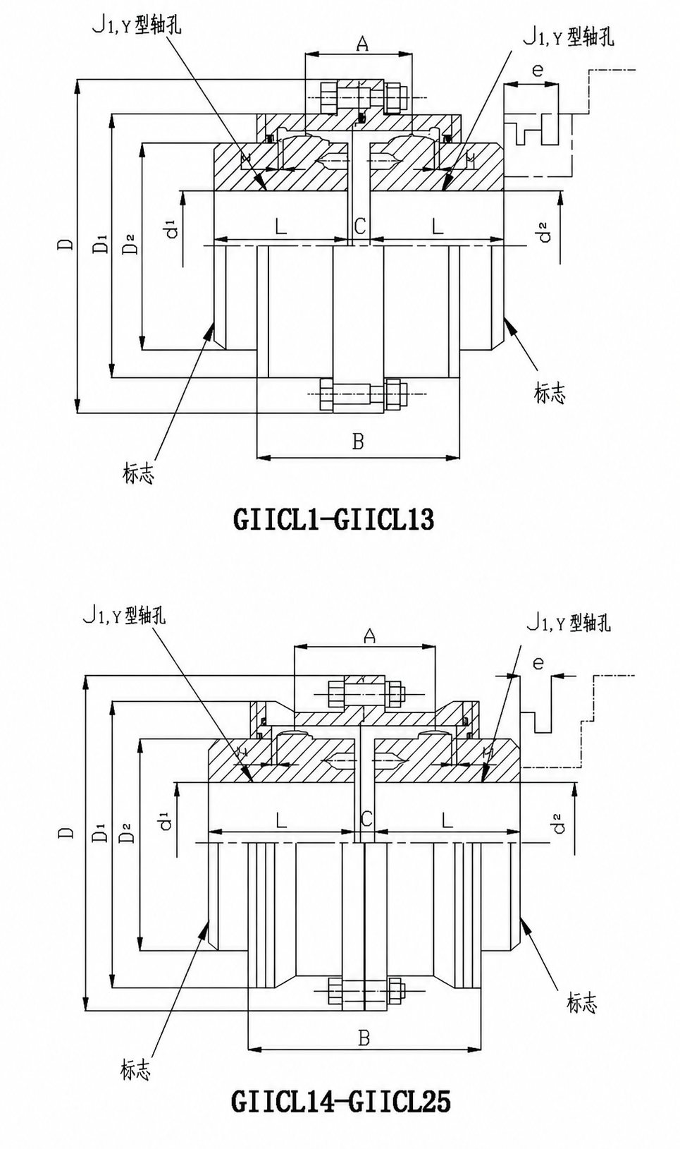
Use each catalogue drawing together with its HTML table. Final torque, speed, bore, material and fit remain subject to the approved project drawing.

GIICL Drum Gear Coupling data sheet

Dimension points to confirm
GIICL Drum Gear Coupling dimension drawing with bore, outside diameter, length and installation confirmation points
Select a thumbnail. Hover or tap the main image to inspect details.

On smaller screens, swipe horizontally or view the compact model cards.

ModelNominal torque Tn kN·mAllowable speed n r/minBore diameterBore length LMain dimensions mmWeight kg
d1,d2YJ1DD1D2CHABe
16,18,1942-5.1
GIICL10.4400020,22,2452381037150823676383
25,2862443.1
30,32,3582603.6
20,22,2452-4.9
GIICL20.71400025,2862441158360824288424.5
30,32,35,3882605.1
40,42,45112846.2
22,2452-7.5
GIICL31.12400025,2862441279575824490427
30,32,35,3882606.9
40,42,45,48,50,55,56112848.6
38826010.1
GIICL41.8400040,42,45,48,50,55,5611284149116908249984212.2
60,63,6514210714.5
GIICL53.15400040,42,45,48,50,55,5611284167134105102.5551084216.4
60,63,65,70,71,7514210719.6
45,48,50,55,561128422.1
GIICL65.00400060,63,65,70,71,75142107187153125102.5561104226.5
80,85,9017213231.2
50,55,561128427.6
GIICL77.1375060,63,65,70,71,75142107204170140102.5601184233.1
80,85,90,9517213239.2
100,(105)21216747.5
55,561128435.5
GIICL810.00330060,63,65,70,71,75142107230186155123671424742.3
80,85,90,9517213249.7
100,110,(115)21216760.2
60,63,65,70,71,7514210755.6
GIICL916300080,85,90,95172132256212180123691464765.6
100,110,120,12521216779.6
130,(135)25220295.8
65,70,71,7514210772
GIICL1022.4265080,85,90,95172132287239200143.5781644784.4
100,110,120,125212167101
130,140,150252202119
70,71,7514210797
80,85,90,95172132114
GIICL1135.52350100,110,120,125212167325276235143.58117047138
130,140,150252202161
160,170,(175)302242189
75142107128
80,85,90,95172132150
GIICL12502100100,110,120,1252121673623132701648919049205
130,140,150252202213
160,170,180302242248
190,200352282285
150252202269
GIICL13711850160,170,180,(185)302242412350300184.59820849315
190,200,220,(225)352282360
170,180,(185)302242421
GIICL141121650190,200,220352282462418335225.517229663476
240,250410330544
190,200,220352282608
GIICL151801500240,250,260410330512465380225.518231663696
280,(285)470380786
220352282799
GIICL162501300240,250,26041033058052243028720935467913
280,300,3204703801027
250,2604103301176
GIICL173551200280,(290),300,320470380644582490287198364671322
340,360,(365)5504501532
280,(295),300,3204703801698
GIICL185001050340,360,380550450726654540288222430751948
4006505402278
300,3204703802249
GIICL19710950340,(350),360,380,(390)550450818748630328232440752591
400,420,440,450,460,(470)6505403026
360,380,(390)5504503384
GIICL201000800400,420,440,450,4606505409288387203210.5247470753984
480,5003984
530,(540)8006804430
400,420,440,450,4606505404977
GIICL211400750480,50010229288104011.5255490754977
530,560,6008006806152
450,460,480,5006505406318
GIICL221800650530,560,600,630800680113410369154013262510757738
670,(680)9007807738
GIICL232500600530,560,600,6308006801282117810305014.52995808010013
670,(700),710,750,(770)90078011553
560,600,63080068012915
GIICL243550550670,(700),710,7509007801428132211755016.53176108015015
800,850100088016615
670,(700),710,75090078019837
GIICL254500460800,850100088016441538139050193256208022381
900,950-98024765
1000,(1040)-100027797

FAQ

Product Selection FAQ

Can the Drum Gear Coupling be customized from a drawing or old part?

Yes. We can confirm bore, keyway, material, heat treatment, balancing grade, surface treatment and export packing by drawing or old part photos.

What information is needed before quotation?

Please send torque or motor power, speed, shaft diameter, keyway, equipment type, working condition, quantity, drawings or old coupling photos.

Can it replace an imported coupling brand?

Replacement is evaluated after checking dimensions, torque, material, installation space and working condition. Final drawings should be confirmed before production.

What applications are a good fit for the Drum Gear Coupling?

Recommended for steel rolling mills, cranes, mining drives and port handling equipment.

What should be checked during installation and maintenance?

Check shaft alignment, bore and keyway fit, fastener tightening, seals and the specified lubrication condition. Reinspect tooth contact, lubricant condition and abnormal noise during planned maintenance.

Engineering data

Send an Engineering RFQ

Complete the contact step first, then add the operating data you already know. Unknown engineering values do not block submission.

12
Contact
Upload Drawing & Get QuoteAsk on WhatsApp