czahlzq@163.com+86 151 3177 0577

Industrial Coupling

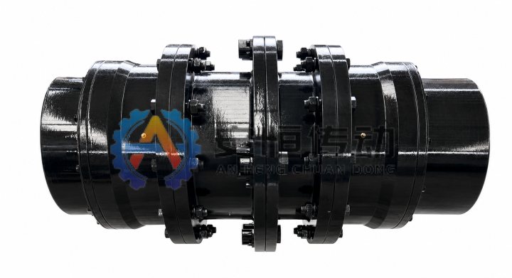
Elastic Pin Gear Coupling

Designed for mixers, crane travel drives, slitting lines and frequently started auxiliary drives; elastic cushioning combined with useful torque capacity.

  • Gear and pin advantages combined
  • High torque transmission
  • Buffers vibration
Series
LZ
Model entries
23
HTML tables
1
Drawings / files
4

No drawing? Send old coupling photos, nameplate details and shaft dimensions.

Documented engineering data

Product Overview and Application Boundary

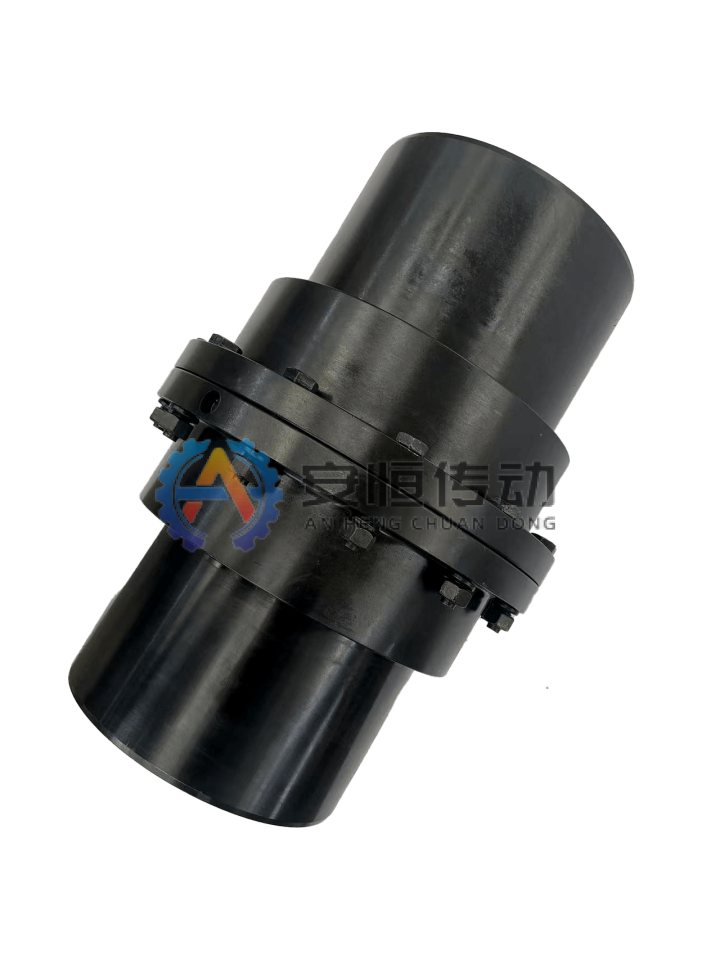
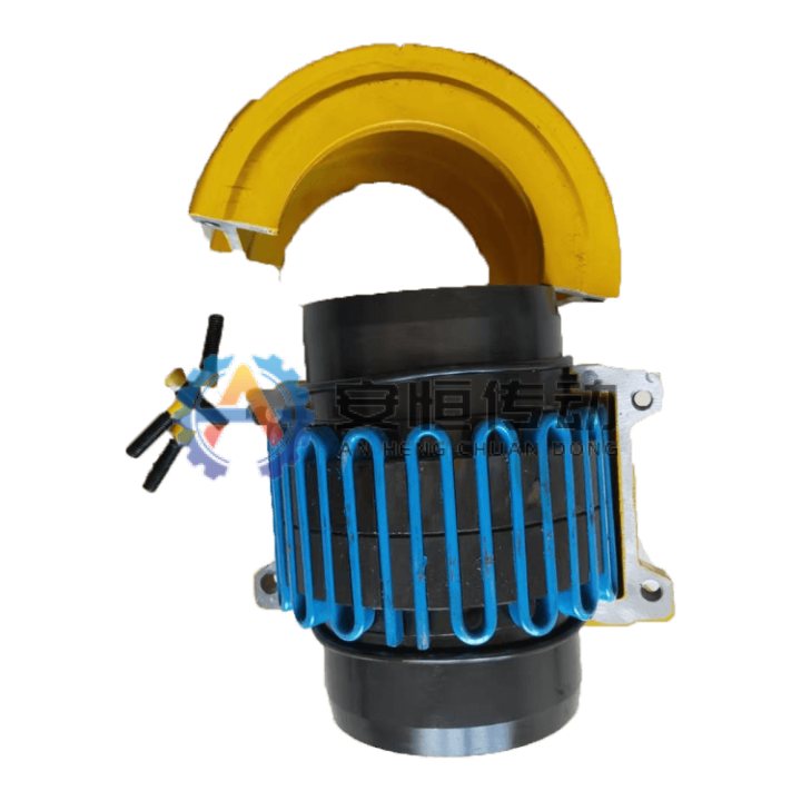
An elastic pin gear coupling combines gear-type hubs, an outer sleeve, pins, elastic elements and fasteners. Based on a gear connection, it adds elastic cushioning to transmit relatively high torque while absorbing start-stop impact, light shock and installation deviation. It is used on reducers, mixers, conveyors, crane travelling mechanisms and slitting or cut-to-length line auxiliary drives. Selection should check torque, speed, shaft diameter, keyway, allowable offset, elastic element material and site dust or temperature conditions. For replacement, outside diameter, overall length and bolt connection dimensions must be verified.

Typical use

Recommended for mixers, crane travel drives, slitting lines and frequently started auxiliary drives.

Selection focus

Confirm torque, speed, shaft diameter, keyway, service factor, misalignment and working environment before selection.

Custom options

Bore, keyway, material, heat treatment, dynamic balancing, surface treatment and export packing can be customized.

Material and inspection

Common materials include 45 steel, 42CrMo or project-specified grades; inspection records can be supplied on request.

Manufacturing Control

Machining, Heat Treatment and Inspection Process for Elastic Pin Gear Coupling

This route follows Elastic Pin Gear Coupling from drawing and material review through blank preparation, CNC rough machining, feature machining, heat treatment, reinspection, finish machining, assembly and final release. The approved drawing determines the exact material and treatment route.

Manufacturing and inspection flowchart for Elastic Pin Gear Coupling
Typical machining and heat-treatment route for Elastic Pin Gear Coupling; drawing-specific operations are released only after technical approval.
  1. 01. Drive data and drawing review: Confirm torque, speed, shaft interfaces, alignment allowance, acceptance criteria and the approved drawing before release.
  2. 02. Material certificate and blank inspection: Verify material identity, certificate, heat number, blank dimensions and the specified forging, casting or bar-stock route.
  3. 03. Saw cutting and forging/casting blank preparation: Saw-cut the stock or prepare the forging/casting blank, remove scale, transfer traceability marks and retain machining allowance.
  4. 04. CNC rough turning of faces, diameters and bores: Use CNC or vertical lathes to rough-turn faces, outside diameters, bores and datum shoulders, leaving allowance for heat-treatment distortion and finishing.
  5. 05. Gear-body tooth cutting and pin-group machining: Machine the named teeth, grooves, holes, splines or mechanism features by turning, milling, hobbing, shaping, drilling, boring or grinding as specified.
  6. 06. Pin turning and elastic-bush batch inspection: Manufacture or verify the spring, pin, bearing, friction or elastomer element to the released specification, with batch traceability where required.
  7. 07. Pin and load-part Q&T/surface hardening: Quench and temper pins and load-carrying steel parts; apply local induction or surface hardening only where the drawing specifies wear-resistant zones.
  8. 08. Hardness, distortion and NDT reinspection: Check hardness, effective case where applicable, distortion and surface condition; perform UT, MT or PT when required before final machining.
  9. 09. Bore, keyway and fit finishing: Finish-turn or grind datum faces and fits, then bore the shaft holes and machine keyways, splines, seal seats or mounting interfaces to the approved tolerances.
  10. 10. Elastic-element fit and final assembly inspection: Verify dimensions, runout, tooth or component fit and controlled assembly; record lubrication, fastener, balance or functional checks applicable to the product.
  11. 11. Final inspection, marking and release: Complete final inspection, traceability marking, rust protection and packing only after the required records and acceptance results are complete.

Documented engineering data

Selection Information to Confirm

Final model selection is based on the actual drive data and approved drawing. Provide the items you already know; unknown values can be reviewed by engineering.

Upload Drawing & Get Quote
  1. 01Required torque or motor power and service factor
  2. 02Operating speed, peak load, starts and reversing duty
  3. 03Shaft diameters d1/d2, keyways and fit requirements
  4. 04DBSE, overall length and available installation space
  5. 05Temperature, dust, moisture, corrosion and maintenance access
  6. 06Existing drawing, old part photo, nameplate or measured dimensions

Documented engineering data

Model and Dimension Data

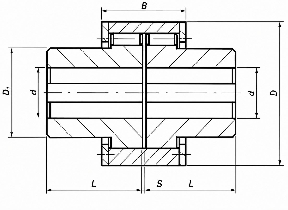
Use each catalogue drawing together with its HTML table. Final torque, speed, bore, material and fit remain subject to the approved project drawing.

LZ Elastic Pin Gear Coupling data sheet

Source: GB/T5015-2003
Dimension points to confirm
LZ Elastic Pin Gear Coupling dimension drawing with bore, outside diameter, length and installation confirmation points
Select a thumbnail. Hover or tap the main image to inspect details.

On smaller screens, swipe horizontally or view the compact model cards.

ModelNominal torque Tn kN·mAllowable speed n r/minBore diameterBore length LMain dimensions mmMoment of inertia kg·m²Weight kg
DD1BS
LZ1(ZL1)0.112500012-2427-527640422.50.0011.67
LZ2(ZL2)0.25500016-3230-829050502.50.0033.00
LZ3(ZL3)0.63450025-4244-11211865703.00.0127.31
LZ4(ZL4)1.8420040-6084-142158909040.04516.20
LZ5(ZL5)4.5400050-8084-1721921209040.10827.02
LZ6(ZL6)8330060-95107-17223013011250.24240.89
LZ7(ZL7)11.2290070-110107-21226016011250.44359.60
LZ8(ZL8)18250080-130132-25230019012860.90894.67
LZ9(ZL9)25230090-150132-25233522015071.733138.1
LZ10(ZL10)31.52100100-170167-30235524515282.422169.3
LZ11(ZL11)402000110-180167-30238026017283.369203.1
LZ12(ZL12)631700130-200202-35244529018286.524296.6
LZ13(ZL13)1001500150-240202-410515345218814.19469.2
LZ14(ZL14)1251400170-260242-410560390218821.67621.7
LZ15(ZL15)1601300190-300282-4705904202401029.52730.5
LZ16(ZL16)2501000220-340282-5506954902651062.471144
LZ17(ZL17)315950240-380330-55077055028510106.01557
LZ18(ZL18)450850250-420330-65086060530013175.42062
LZ19(ZL19)630750280-450380-65097069532214323.23068
LZ20(ZL20)1120650320-500380-650116080035515669.44715
LZ21(ZL21)1800530380-630450-800144010203601818808699
LZ22(ZL22)2240500420-750540-900152011004051925969437
LZ23(ZL23)2800460480-850540-10001640124044020398212095

Documented engineering data

Product Documents and Drawing Files

Only files currently linked to this product are listed. Request the required model if the correct revision is not shown.

FAQ

Product Selection FAQ

Can the Elastic Pin Gear Coupling be customized from a drawing or old part?

Yes. We can confirm bore, keyway, material, heat treatment, balancing grade, surface treatment and export packing by drawing or old part photos.

What information is needed before quotation?

Please send torque or motor power, speed, shaft diameter, keyway, equipment type, working condition, quantity, drawings or old coupling photos.

Can it replace an imported coupling brand?

Replacement is evaluated after checking dimensions, torque, material, installation space and working condition. Final drawings should be confirmed before production.

What applications are a good fit for the Elastic Pin Gear Coupling?

Recommended for mixers, crane travel drives, slitting lines and frequently started auxiliary drives.

What should be checked during installation and maintenance?

Check shaft alignment, bore and keyway fit, fastener tightening and the condition of the elastic element. Replace the elastic element if cracking, hardening, permanent deformation or abnormal clearance is found.

Engineering data

Send an Engineering RFQ

Complete the contact step first, then add the operating data you already know. Unknown engineering values do not block submission.

12
Contact
Upload Drawing & Get QuoteAsk on WhatsApp