
Technical Articles
Universal Joint Coupling Working Angle: 6 Checks
What does working angle mean in a universal joint coupling?
The working angle is the angle between the connected shaft centerlines while the universal joint coupling is transmitting torque. It is not the same as the angle measured when the machine is stopped with no load. A correct selection must consider the running angle, speed, telescopic movement, torque, flange connection and lubrication access at the same time.
Quick answer: Before ordering a cardan shaft or universal joint coupling, confirm the maximum working angle at operating position, the change in angle through the stroke, the required telescopic length, shaft speed, torque, flange pilot and bolt pattern. The selected cross-bearing and tube assembly must be checked against the actual drive position, not only the motor nameplate.
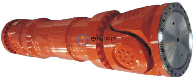
1. Measure the angle at the real operating position
Measure the angle between the driving and driven shaft axes at the position where the machine transmits load. For a rolling mill, the angle can change as the stand, screwdown, straightener or telescopic shaft moves. Record the cold position, hot position and the maximum position during adjustment. A single workshop measurement can miss the condition that controls bearing life.
State whether the angle is constant, oscillating or continuously changing. A universal joint coupling used with a long shaft line may also need a telescopic spline to accommodate axial movement. The roughing mill universal joint coupling article and finishing mill universal joint coupling article cover narrower steel-line applications; this guide focuses on the measurement logic that applies before quotation.
2. Confirm torque and speed at the coupling shaft
Motor power alone does not define the cardan shaft load. Identify the coupling shaft speed after any gearbox and calculate the steady torque with T = 9550P / n, where P is transmitted power in kW and n is shaft speed in r/min. Then review startup, reversing, braking, bite-in, jam and torsional vibration conditions that can create short-duration peaks.
The cross assembly, yokes, flange bolts and spline must transmit the same load case. If peak torque data are unavailable, label the estimate as an engineering assumption and confirm it with the equipment designer. Do not increase the coupling size without checking the shaft, bearing, guard and flange interfaces that carry the load around it.
3. Check telescopic movement and spline length
A universal joint coupling may need to shorten or extend as the machine moves. Provide the minimum and maximum shaft-end distance, required telescopic stroke, spline engagement length at both limits and the position where the highest torque is transmitted. Insufficient spline engagement can cause edge loading, fretting or loss of effective torque capacity.
The RFQ should state whether the shaft is installed horizontally or vertically, whether it is supported by a bearing, and whether the coupling must be removed through a restricted guard opening. These installation details often determine the tube length, yoke form and service access more than the nominal series code.
4. Verify flange, pilot and bolt-circle interfaces
Record flange pilot diameter, bolt-circle diameter, bolt count, bolt size, face runout, flange thickness and the direction of assembly on both ends. Also confirm the available wrench clearance and whether the existing flange can be reused. A universal joint coupling with the correct working angle is still unsuitable if the flange pilot or bolt pattern cannot be aligned without site modification.
For an imported or obsolete drive, photographs should show the complete flange, shaft support, guard and removal path. If the old part has been repaired or re-drilled, separate current measured dimensions from the original drawing. A Custom Replacement Coupling may preserve the interface, but the drawing must define the load path and balance requirements.
5. Select cross-bearing, balance and lubrication requirements
Cross-bearing size and arrangement must match working angle, speed, load cycle and expected contamination. State whether the coupling needs grease replenishment points, sealed cross bearings, a specified balancing grade or a complete-assembly balance report. At higher speed, imbalance or a worn bearing can create vibration that is incorrectly blamed on the working angle alone.
During inspection, check bearing temperature, grease leakage, needle-bearing play, yoke cracks, flange bolt witness marks, spline wear and tube runout. Record the angle and operating speed when abnormal vibration appears. The universal joint coupling product page lists the product family, while the final service limits must come from the selected drawing.
6. Prepare an RFQ that allows a safe selection
Send the equipment name and drive position, power, coupling-shaft speed, operating torque, maximum working angle, angle variation, telescopic stroke, minimum spline engagement, flange pilots, bolt circles, shaft support arrangement, ambient conditions, quantity and photographs. Include the shutdown date and the direction in which the old shaft must be removed.
For rolling mill projects, add the stand or straightener position, hot alignment information, bite or reversing history and any previous cross-bearing or spline failures. Anheng can then compare a standard Universal Joint Coupling with a custom interface instead of quoting a shaft length from incomplete data.
Common working-angle selection mistakes
- Using the stationary angle while ignoring the maximum running angle.
- Calculating torque from motor power without using the speed at the coupling shaft.
- Omitting telescopic stroke or minimum spline engagement from the drawing.
- Checking the coupling body but not the flange pilot, bolts, bearings and guard.
- Treating a crowned or articulated joint as permission to exceed the selected angle limit.
FAQ | Universal Joint Working Angle
Is the working angle the only selection parameter?
No. Working angle must be checked with torque, speed, angle variation, telescopic movement, spline engagement, flange interfaces, balance and lubrication. The maximum value at the real operating position is more useful than a single unloaded measurement.
What information is needed for a cardan shaft quotation?
Provide power, speed at the coupling shaft, operating torque, maximum angle, telescopic stroke, flange pilots and bolt circles, shaft support, installation photos, quantity and required delivery date. A marked-up drawing is preferred for replacement work.
Can an existing flange be reused?
Sometimes, but the pilot, bolt pattern, face runout, material, torque path and balance must be verified. Reusing a flange is not safe to assume from a similar-looking photograph.
Need an engineering selection or replacement review?
Send power, speed, shaft diameters, keyway, installation dimensions, drawings or old-part photos. We will review the working condition before confirming the model and quotation.