liujinsong@czahlzq.com+86 151 3177 0577

Industrial Coupling

Rigid Coupling

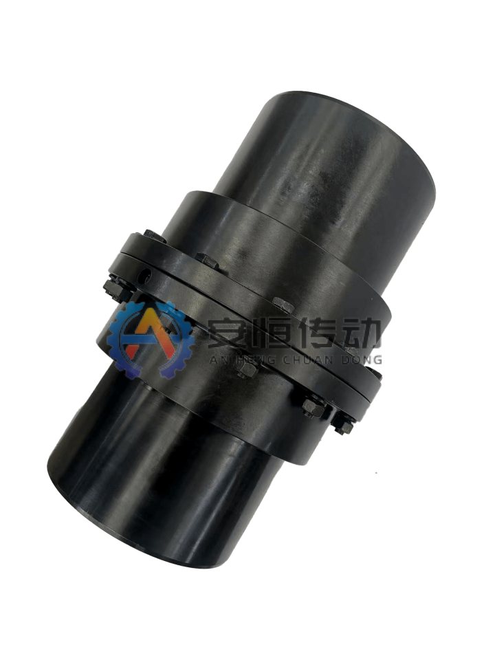
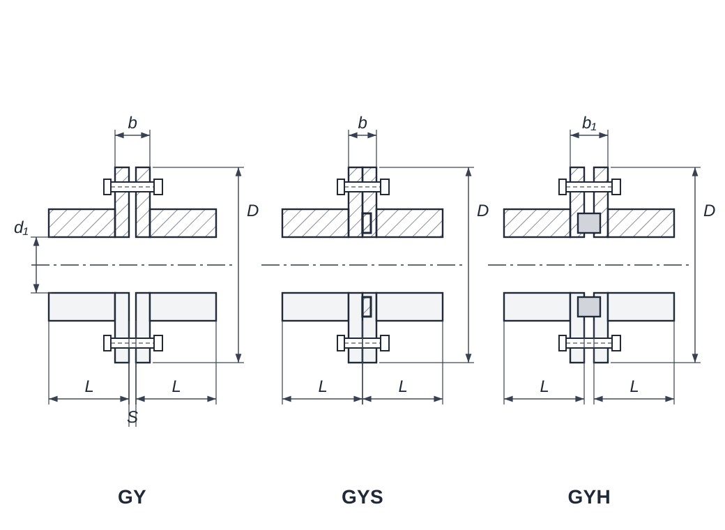
Flange couplings GY, GYS and GYH (GB/T 5843-2003) and JQ clamp couplings join two accurately aligned shafts into one. No elastic parts, no lubrication and no backlash.

  • No elastic parts, no lubrication
  • Torque passed without backlash
  • GY, GYS, GYH flange types to GB/T 5843-2003
  • JQ clamp type fits without moving the shafts
Series
GY1 / GY2 / GY3 / GY4 / GY5 / GY6 / GY7 / GY8
Model sizes
39
Data tables
2
Drawings & catalogues
2

No drawing? Send old coupling photos, nameplate details and shaft dimensions.

Engineering data

Overview and Where It Fits

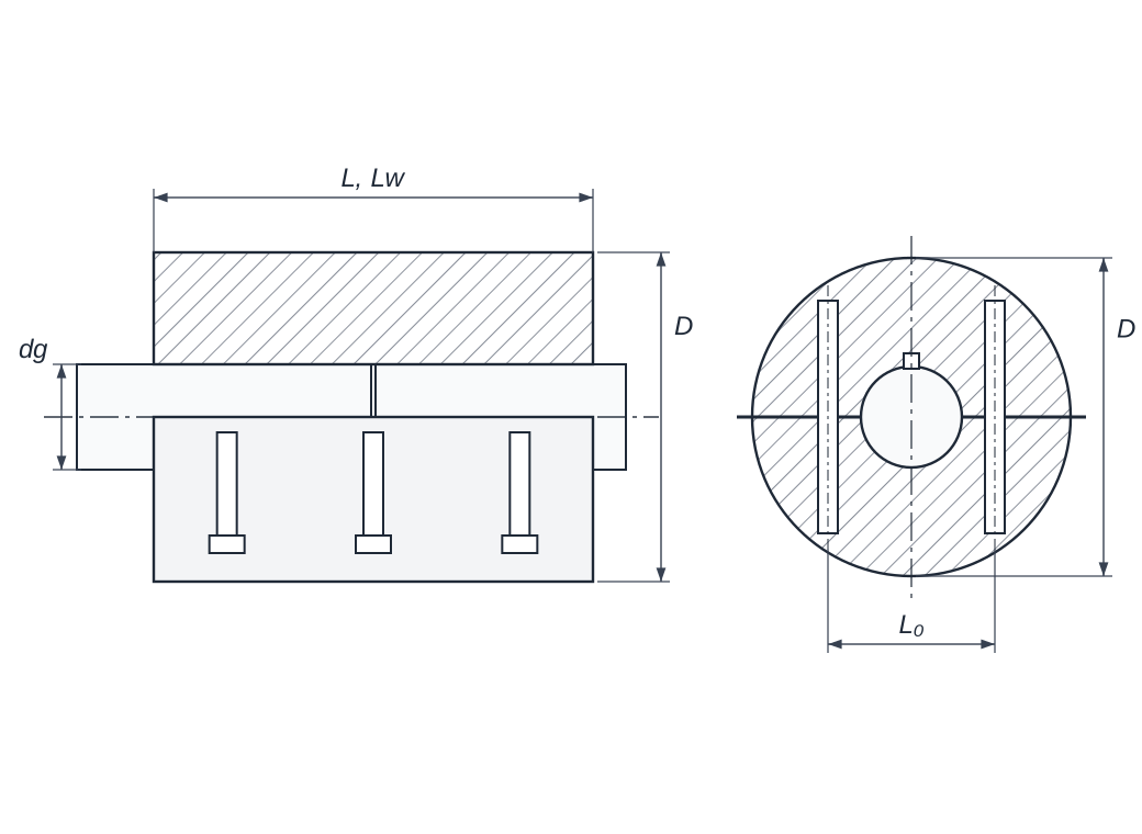
A rigid coupling joins two shafts so that they turn as one. It has no elastic element and nothing to lubricate, and it passes torque without backlash. Because it cannot take up misalignment, both shafts must be accurately aligned and stay aligned in service, for example on one rigid base. We make two kinds. Flange couplings to GB/T 5843-2003 come in sizes GY1 to GY13: 25 N·m to 100,000 N·m nominal torque and bores from 12 mm to 250 mm. GY centres the two halves with fitted (reamed) bolts, so you can take it apart without moving either shaft. GYS centres them with a spigot and recess, which is simpler to machine but needs axial room to dismantle. GYH uses a centring ring. JQ and JQW clamp couplings (HG5-213-65, bores 25 mm to 200 mm) are split along their length: the two half-shells are bolted around both shaft ends, so neither shaft has to move. The standard sizes are for two shafts of the same diameter. Before we quote, please send the torque or power and speed, both shaft sizes with keyways, and the type you need. Is your old coupling marked YL or YLD? Send us the nameplate and we will match it.
Typical use

Shafts accurately aligned on one rigid base and running without heavy shock: line shafts, low-speed heavy drives and vertical shafts.

Sizes and torque

GY1 to GY13 (GB/T 5843-2003): nominal torque 25 N·m to 100,000 N·m, bores 12 mm to 250 mm, speed up to 12,000 rpm. JQ (HG5-213-65): bores 25 mm to 200 mm, max. torque 90 N·m to 33,750 N·m.

Types

GY: fitted bolts, dismantled without moving the shafts. GYS: spigot centring, needs axial room to dismantle. GYH: centring ring. JQ and the shorter JQW: split clamp shells.

Bores and alignment

GY: Y or J1 bores to GB/T 3852, taper bores on request, keyways to your drawing. A rigid coupling takes no misalignment, so align both shafts accurately.

Engineering data

Selection Information to Confirm

Final model selection is based on the actual drive data and approved drawing. Provide the items you already know; unknown values can be reviewed by engineering.

Upload Drawing & Get Quote
  1. 01Required torque or motor power and service factor
  2. 02Operating speed, peak load, starts and reversing duty
  3. 03Shaft diameters d1/d2, keyways and fit requirements
  4. 04DBSE, overall length and available installation space
  5. 05Temperature, dust, moisture, corrosion and maintenance access
  6. 06Existing drawing, old part photo, nameplate or measured dimensions

Engineering data

Model and Dimension Data

Use each catalogue drawing together with its data table. Final torque, speed, bore, material and fit remain subject to the approved project drawing.

Choose a type

GY, GYS, GYH Flange Coupling data sheet (GB/T 5843-2003)

30 sizes | Source: GB/T 5843-2003
Dimension points to confirm
GY, GYS and GYH flange coupling dimension drawing
Select a thumbnail. Hover or tap the main image to inspect details.

On smaller screens, swipe horizontally or view the compact model cards.

ModelNominal torque Tn N·mMax. speed n r/minBore d1, d2 mmBore length L mmDimensions mmInertia kg·m²Weight kg
Y typeJ1 typeDbb1S
GY1251200012,14322780264260.00081.16
16,18,194230
16,18,194230
GY2631000020,22,24523890284460.00151.72
256244
GY3112950020,22,245238100304660.00252.38
25,286244
GY4224900025,286244105324860.0033.15
30,32,358260
GY5400800030,32,35,388260120365280.0075.43
40,4211284
GY69006800388260140405680.0157.59
40,42,45,48,5011284
GY71600600048,50,55,5611284160405680.03113.1
60,63142107
GY83150480060,63,65,70,71,751421072005068100.10327.5
80172132
75142107
GY96300360080,85,90,951721322606684100.31947.8
100212167
GY1010000320090,951721323007290100.72082.0
100,110,120,125212167
120,125212167
GY11250002500130,140,1502522023808098102.278162.2
160302242
150252202
GY12500002000160,170,18030224246092112125.923285.6
190,200352282
GY131000001600190,200,2203522825901101301219.978611.9
240,250410330

Data to GB/T 5843-2003. GY, GYS and GYH of the same size share one row, listed under GY (GY6 also covers GYS6 and GYH6); b1 is for GYH. Weight and inertia are for GY with Y/J1 bores and the smallest bore. Bores and keyways are machined to your drawing; taper bores on request.

JQ, JQW Clamp Coupling data sheet (HG5-213-65)

Clamp (split muff) | 26 sizes | Source: HG5-213-65
Dimension points to confirm
JQ and JQW clamp coupling dimension drawing
Select a thumbnail. Hover or tap the main image to inspect details.

On smaller screens, swipe horizontally or view the compact model cards.

ModelBore dg (H7) mmMax. torque Mmax N·mD mmJQJQWL0 mmWeight kg
L mmBolts n–d0Lw mmBolts n–d0
JQ-252590951104-121004-12584.47
JQ-3030901021304-141104-14644.47
JQ-35352361181626-141154-14807.60
JQ-40402361181626-141154-14807.60
JQ-45455301351906-141354-1410010.85
JQ-50505301351906-141354-1410010.85
JQ-55555301351906-141354-1410010.85
JQ-606014001722508-181956-1812425.06
JQ-656514001722508-181956-1812425.06
JQ-707014001722508-181956-1812425.06
JQ-808026501852808-182206-1813830.16
JQ-858526501852808-182206-1813830.16
JQ-909052002303308-232556-2317056.38
JQ-959552002303308-232556-2317056.38
JQ-10010052002303308-232556-2317056.38
JQ-10510552002303308-232556-2317056.38
JQ-11011090002603908-233006-2320090
JQ-11511590002603908-233006-2320090
JQ-12012090002603908-233006-2320090
JQ-1251251500028044010-233608-23210125
JQ-1301301500028044010-233608-23210125
JQ-1401401500030044010-273608-23230140
JQ-1501502800034050010-334058-33260215
JQ-1601602800034050010-334058-33260215
JQ-1801803100038056010-334608-33300350
JQ-2002003375042064010-335408-33340516

Data to HG5-213-65. Each size joins two shafts of the same diameter dg. JQW is the shorter version: read its length Lw and bolts in the JQW columns. L0 is the centre distance of the bolts on the two sides. Ask us for the shaft-end details before you machine the shafts.

FAQ

Product Selection FAQ

When should I use a rigid coupling instead of a flexible one?

Only when both shafts are accurately aligned and stay that way, for example on one rigid base with little relative movement. A rigid coupling takes no misalignment, so any offset loads the bearings and shafts. If the machines can move relative to each other, choose a gear, disc or other flexible coupling.

What is the difference between GY, GYS and GYH?

They share the sizes, torques and main dimensions in the table; only the centring differs. GY uses fitted (reamed) bolts, so it can be taken apart without moving either shaft. GYS has a spigot and recess, which is easier to machine, but one shaft must move back to separate the halves. GYH centres the halves on a separate ring.

My old coupling is marked YL or YLD. Can you replace it?

Yes. YL and YLD are names from the older GB 5843-86 standard (YL also appears in JB/ZQ 4376-86); GB/T 5843-2003 replaced them with GY and GYS. The sizes do not match one to one, so send us the nameplate, a photo or the old drawing with both shaft sizes, and we will match it to a current size or make it to the old dimensions.

Can a clamp coupling be fitted without moving the motor or gearbox?

Yes. The JQ shell is split along its length, so the two halves are placed around both shaft ends and bolted together; neither shaft has to move. The standard sizes are for two shafts of the same diameter. Ask us for the shaft-end details before you machine the shafts.

What do you need from me for a quote?

The torque or motor power and speed, both shaft diameters and keyways, and the type: GY, GYS, GYH, JQ or JQW. For flange couplings, add the bore type (Y or J1). Please also tell us the quantity.

Engineering data

Send an Engineering RFQ

Complete the contact step first, then add the operating data you already know. Unknown engineering values do not block submission.

12
Contact
Upload Drawing & Get QuoteAsk on WhatsApp