
Technical Articles
How Do You Select a Gear Coupling for Heavy-Duty Equipment? An Engineering Approach from Torque to Shaft Bores
Start with the drivetrain, not a model chosen directly from motor power
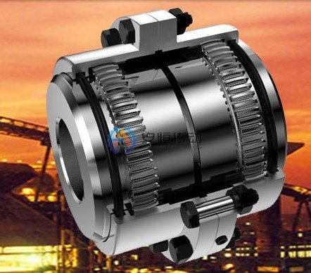
A Gear Coupling suits low- to medium-speed, high-torque drives where installation space is limited and regular lubrication is practical. The correct selection sequence is: confirm the actual load, calculate base torque, account for startup and shock loads, check shaft bores and keyways, verify misalignment capacity, operating speed, and available space, define lubrication and maintenance requirements. Giving a supplier only the motor power can produce a coupling with adequate torque capacity but insufficient shaft bore size, or one that fits the available space but lacks adequate shock-load margin.
Step 1: Separate operating torque from abnormal peaks
When motor power `P` (kW) and operating speed `n` (r/min) are known, theoretical torque under steady operating conditions can be estimated as follows:
T = 9550P / n
This result is only the base torque at the input, not the final selection torque. Also verify whether the application involves direct-on-line motor starting, variable-frequency soft starting, frequent reversing, starting under load, material jams, braking, or inertial loads. The service factor should come from the relevant product catalog or be determined by engineers from load records. Do not apply one factor to every heavy-duty machine. If historical peak data are available from the PLC, motor protection relay, or torque-monitoring system, use the site data as the primary basis for verification.
| Required data | Why it affects selection | Data source |
|---|---|---|
| Continuous motor power and operating speed | Determines base torque and operating-speed rating | Motor nameplate, gear ratio, equipment manual |
| Startup and peak torque | Establishes the short-duration capacity required of the gear teeth and connecting components | Drive records, process loads, failure history |
| Starts, stops, and reversals per hour | Indicates the severity of shock and fatigue loading | Control logic, shift records |
| Shaft diameter, shaft bore, and keyway | Confirms that the hub can be machined and transmit the required torque | Shaft-end drawing, site measurements |
| Distance between shaft ends (DBSE) and outside-diameter limit | Determines the configuration, overall length, and assembly clearance | General arrangement drawing, guard measurements |
Step 2: A machinable shaft bore does not guarantee a strong enough connection
Confirm the shaft diameters `d1/d2`, shaft extension lengths, keyway widths and depths, fit requirements, and whether the connection uses a tapered bore, spline, or locking assembly. A large shaft bore reduces hub wall thickness, while a large coupling on a small shaft may increase rotational inertia. The key and keyway must also withstand peak startup torque. If the old component shows a crushed keyway, a cracked hub, or fretting wear in the shaft bore, do not simply move up to a larger coupling. Reassess the shaft-end connection design.
If reliable drawings are unavailable for existing equipment, first establish a dimensional baseline using the guide to measuring an old coupling for replacement. If a non-standard flange or special shaft bore must be retained, then evaluate a Custom Replacement Coupling to avoid copying worn dimensions directly into the new component.
Step 3: Check misalignment capacity, but do not use the coupling as a substitute for alignment
The gear design can accommodate limited angular misalignment, radial misalignment, and axial displacement. Actual allowable values vary with the series, size, tooth geometry, and operating speed, and must be taken from the approved product drawing. Selection data should state cold and hot shaft positions, the risk of foundation settlement, axial movement, and whether the machine has a long intermediate shaft. Operation beyond the allowable misalignment over extended periods causes edge contact on the teeth and transfers additional loads to bearings and seals.
If uneven wear, abnormal heating, or metallic particles in the grease are found, follow the Gear Coupling failure troubleshooting sequence to identify the root cause instead of increasing the service factor again.
Heavy-duty applications that fit, and those that do not
Applications in which a Gear Coupling should be evaluated include rolling-mill auxiliary drives, crane and material-handling systems, low-speed heavy-duty conveyors, metallurgical machinery, and compact gearbox connections. This assumes the site can maintain alignment and carry out seal inspections and scheduled lubrication.
Do not treat a Gear Coupling as the default choice in the following cases:
- For high-speed pumps and fans requiring low vibration and lubrication-free operation, compare a Diaphragm Coupling;
- For drives with severe shock loads that primarily need torsional cushioning, compare a Grid Coupling;
- For equipment that must limit or interrupt torque during a material jam, evaluate a Safety Coupling and Torque Limiter Coupling;
- Where alignment cannot be maintained or seals fail repeatedly, correct the foundation, bearings, or installation conditions first.
Engineering data required before quotation
At a minimum, provide the equipment name and station, motor power, input and output operating speeds, gear ratio, starting method, duty cycle, peak-load or jam records, shaft diameters and keyways, distance between shaft ends (DBSE), allowable outside diameter and overall length, installation orientation, ambient temperature, dust or moisture exposure, original model, and photographs of the old component. Identify any brake drum, adapter flange, intermediate shaft, special flange, or dynamic balancing requirement separately.
After the supplier submits a proposal, verify the rated torque, allowable speed, maximum shaft bore, installation dimensions, allowable misalignment, lubrication method, and wear parts item by item. Do not compare model numbers and prices alone. This approach produces a coupling that meets load, installation, and long-term maintenance requirements together.
FAQ | How Do You Select a Gear for Heavy-Duty Equipment? An Engineering Approach from Torque to Shaft Bores
Should a heavy-duty gear coupling be selected from motor power alone?
No. Use the torque at the coupling location, the peak event, speed, bore, movement and maintenance conditions. Motor power is only one input and cannot confirm the shaft interface.
When is a gear coupling the wrong choice for a heavy-duty drive?
It is the wrong starting point when alignment cannot be maintained, seals cannot be serviced or the load event is outside the approved design. Correct the machine condition or review another coupling family before increasing size.
Need an engineering selection or replacement review?
Send power, speed, shaft diameters, keyway, installation dimensions, drawings or old-part photos. We will review the working condition before confirming the model and quotation.