
Technical Articles
Steel Plant: Drum Gear Coupling Selection Guide
A Drum Gear Coupling for Steel Plant is chosen from the station duty. The name in the catalogue comes later. First write down the load event, the shaft position and the evidence that can be checked after the machine runs.
Start with the station load path: Steel Plant
Record the actual failure location, operating state and any change made to the machine before assigning the cause to the coupling. For Steel Plant, record the installed coupling position and verify plant-wide coupling-family decisions, shock spectrum, maintenance windows and spare strategy against the site record; name the component that must be protected. A drum gear coupling offers high torque capacity and better tooth contact, making it suitable for heavy-duty steel mill drives with unavoidable alignment deviation.
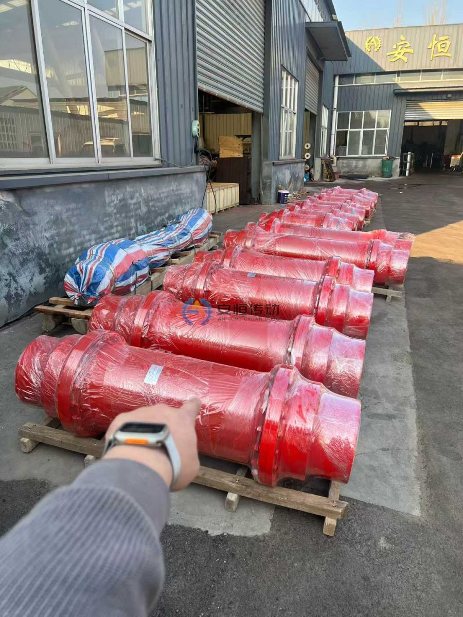
Use the event, not a copied service factor: Steel Plant
Confirm the equipment position, power, speed, shaft ends, keyways, DBSE, movement, environment, protection logic and available drawings. Check tooth hardness, face width, crowned tooth profile, sealing, lubrication and axial movement allowance. Check the current shaft interface, movement and service route instead of treating a catalogue image as installed evidence.
Set the boundary before approval: Steel Plant
Photograph the complete assembly before dismantling and keep the failed component. Compare steel-plant hub, application matrix, shaft section, shock spectrum, maintenance window with the timestamp of the first symptom. If a bore, keyway, guard or seal is worn, preserve the measurement as engineering evidence. A drum gear coupling is not an overload protection device. If jamming or abnormal shock is possible, evaluate torque protection as well.
Keep the evidence with the selection: Steel Plant
If the Steel Plant event cannot be repeated or described, the coupling choice is provisional. Preserve steel-plant hub, application matrix, shaft section and leave the open values visible to the reviewer.
Hand over a usable RFQ: Steel Plant
Send the station, coupling position, normal and abnormal load description, speed, shaft measurements, movement, environment, quantity and drawings or photographs. Use the relevant product data and recorded loads; do not invent a service factor when the event is unknown.
For Steel Plant, after the site data are complete, compare the Drum Gear Coupling product information with the coupling measurement guide and related engineering note.
Questions from the station record: Steel Plant
Which event should control the size decision?
Use the recorded event at the coupling position, including direction, duration, repetition and consequence. A catalogue rating is a starting point, not a substitute for the station record.
What must remain open before approval?
Keep torque, speed, bore, keyway, DBSE, movement and environment marked as site confirmation required until a drawing or measurement supports them.
Need an engineering selection or replacement review?
Send power, speed, shaft diameters, keyway, installation dimensions, drawings or old-part photos. We will review the working condition before confirming the model and quotation.