
Technical Articles
Belt Conveyor Coupling Selection: 7 Engineering Checks
Start with the conveyor duty, not with a coupling model or motor power alone. Record whether the belt starts loaded, how often it starts and stops, whether the material can block the belt, and how much space is available around the shaft ends. A practical selection must then connect the load profile to torque, speed, shaft bores, keyways, alignment and maintenance.
Quick answer: A belt conveyor coupling should be checked against steady torque, starting and jam loads, operating speed, shaft-end interfaces, allowable misalignment and the planned maintenance method. A catalogue model is only suitable after these seven checks agree with the installation.
1. Define the belt conveyor load profile
The same belt speed can produce very different coupling duty. A short conveyor with an empty start is not equivalent to a long belt that starts with material on it. Note loaded starting, reversing, braking, frequent cycling, inclined conveying, material impact and the possibility of a blocked or seized roller. These conditions determine whether the drive needs torsional cushioning, extra peak-torque capacity or separate overload protection.
For a steel plant or quarry conveyor, also record dust, water spray, ambient temperature and the shutdown window. These details affect seals, lubricant access and whether a split housing or removable spacer is needed for service.
2. Calculate base torque and separate abnormal peaks
Use the shaft section carrying the coupling when estimating base torque. With transmitted power P in kW and shaft speed n in r/min, the steady-state estimate is T = 9550P / n in N·m. This is a starting value, not the final coupling rating. Check startup current or torque, belt acceleration, brake torque, jam records and any torque data from the drive or protection relay before selecting a service factor.
Do not hide every uncertainty inside one oversized service factor. If the conveyor has a known jam condition, define the normal peak and the damaging peak separately. If the machine must disconnect during a jam, compare a Safety Coupling or Torque Limiter Coupling instead of expecting a standard flexible coupling to act as an overload device.
3. Confirm speed, bore and keyway as one interface
The coupling must fit both shaft ends and transmit the calculated peak through the actual connection. Provide shaft diameters d1 and d2, shaft extension lengths, bore tolerance or fit, keyway width and depth, key length, hub length, shoulder fillets and the direction of installation. A large bore can reduce hub wall thickness, while a long keyway or damaged shaft shoulder can become the weak point even when the coupling body has enough torque capacity.
For an old installation, do not copy a worn bore or crushed keyway into the replacement. Use the old coupling measurement guide and mark measured values, inferred values and values still requiring confirmation.
4. Check DBSE, guard clearance and removal direction
Distance between shaft ends (DBSE), overall length, outside diameter and guard clearance decide whether a nominally correct coupling can actually be installed. Confirm brake-wheel or disc dimensions, spacer length, flange pilot, bolt-circle diameter, fastener access and the direction in which the coupling must be removed during a shutdown.
A replacement that fits only after moving the motor or cutting the guard is not an interchangeable replacement. Include a simple shaft-line sketch or marked-up photograph with the RFQ. The conveyor coupling application solution shows the type of installation information that should be reviewed before a quotation is finalized.
5. Match the coupling type to the failure risk
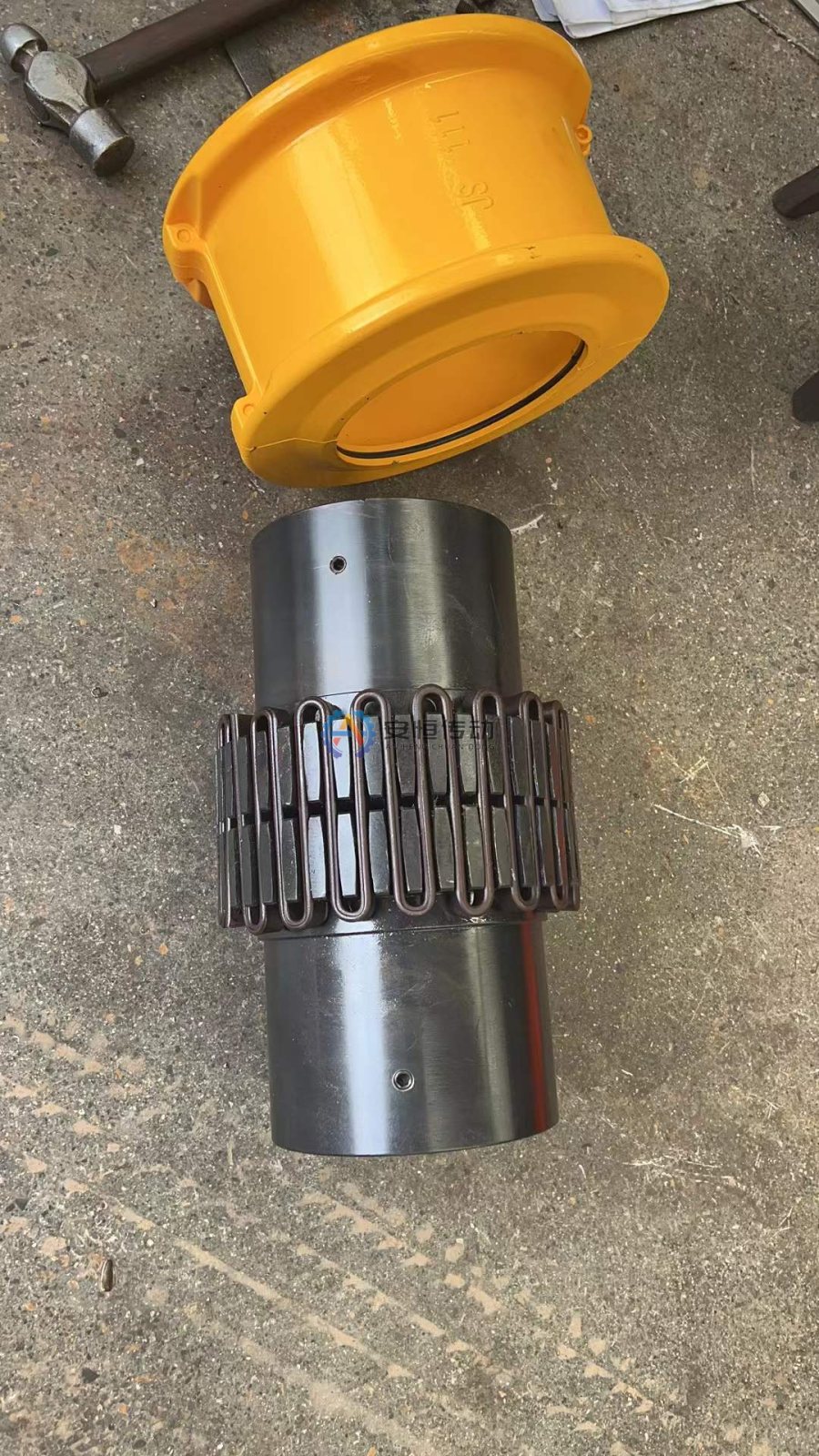
A Grid Coupling is often evaluated when a conveyor needs torsional cushioning and practical maintenance. A Gear Coupling may be considered when torque density and controlled misalignment compensation are more important and lubrication can be maintained. A Custom Replacement Coupling is appropriate when the old shaft interfaces, brake assembly or envelope cannot be matched by a catalogue size.
The choice should follow the risk being controlled. If the recurring problem is belt blockage, first decide whether cushioning or disconnect protection is required. If the recurring problem is one-sided tooth or keyway wear, correct alignment and shaft conditions before simply changing coupling type.
6. Verify alignment and maintenance conditions
A flexible coupling can accommodate defined shaft misalignment; it cannot replace alignment work. State cold and hot shaft positions, expected axial displacement, angular or radial offset, foundation movement and the condition of the connected bearings. Confirm the allowable values from the selected model drawing, because limits vary by series, size, speed and operating temperature.
For maintenance, specify lubricant grade or wear element, filling access, seal inspection, guard removal and the planned inspection interval. After the first loaded run, recheck alignment, fastener witness marks, temperature, vibration, lubricant leakage and any contact between the coupling and guard.
7. Send an RFQ that allows an engineering decision
A useful belt conveyor coupling RFQ includes the equipment name and position, motor power, operating speed at the coupling shaft, reducer ratio, starting method, loaded-start condition, peak or jam history, shaft diameters, keyways, DBSE, outside-diameter and length limits, environment, quantity, delivery target and photographs of the old coupling and guard.
For a faster quotation, attach the nameplate, both shaft ends, the installed coupling from several angles and any drawing or catalogue page. Anheng can then compare a standard Grid Coupling, a Gear Coupling or a custom replacement route against the real interfaces rather than guessing from motor power.
Common selection mistakes to avoid
- Choosing by motor power while ignoring the coupling shaft speed and reducer ratio.
- Copying a worn bore, keyway or bolt pattern without checking the shaft and hub condition.
- Treating a flexible coupling as a jam-release or overload-protection device.
- Using a catalogue misalignment value without checking the selected size and speed.
- Omitting DBSE, guard clearance or removal direction until after the quotation.
FAQ | Belt Conveyor
Can a belt conveyor coupling be selected from motor power alone?
No. Motor power helps establish base torque, but the selection also requires shaft speed, startup and jam loads, shaft bores, keyways, DBSE, alignment, environment and the required protection response.
Which coupling data should be measured on an old conveyor?
Measure both shaft diameters, keyways, shaft extensions, hub lengths, DBSE, overall length, outside diameter, flange or brake interfaces and guard clearance. Add photographs so worn or inaccessible dimensions can be checked.
Should a grid coupling or gear coupling be used on a conveyor?
Either may be suitable depending on shock load, torque density, misalignment, lubrication access and the shaft interfaces. Compare the actual duty and maintenance plan rather than choosing from the product name alone.
Need an engineering selection or replacement review?
Send power, speed, shaft diameters, keyway, installation dimensions, drawings or old-part photos. We will review the working condition before confirming the model and quotation.