Technical Articles
Grid or Gear Couplings for Crushers and Conveyors?
Quick Answer: Decide Whether Shock Damping or High-Torque Transmission Matters More
When the priority is to reduce the effect of startup, reversing, or material impact on the gearbox, first evaluate a Grid Coupling. For low-speed, high-torque duty with limited radial space and reliable on-site lubrication, first evaluate a Gear Coupling. If the drive must slip or disengage during a jam, neither can replace a Safety Coupling or Torque Limiter Coupling.
Engineering Differences Between the Two Designs
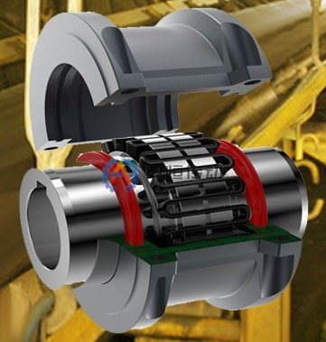
| Comparison | Grid Coupling | Gear Coupling |
|---|---|---|
| Primary feature | The grid flexes within the hub grooves to provide torsional damping | Internal and external gear teeth provide high torque capacity per unit volume |
| Better suited to | Reducing startup loads and short-duration impacts | Transmitting higher torque within limited space |
| Stiffness | More torsionally flexible | Relatively stiffer; shock damping should not be its main selling point |
| Maintenance focus | Grid, cover, grooves, and lubrication | Tooth flanks, seals, cover, and lubrication |
| Failure indicators | Grid breakage, groove indentation, or grease thrown from the cover | Uneven tooth wear, pitting, seal leakage, or increased backlash |
| Common limitations | Both require controlled alignment; most designs require specified lubrication; standard versions are not overload-disconnect devices |
This table only narrows the options. It does not replace checks of rated torque, allowable speed, maximum shaft bore, and allowable misalignment for the specific coupling size.
Crushers: Identify the Impact Source and Consequences of a Jam
Jaw, cone, hammer, and roll crushers do not have the same load profile. Before requesting a quotation, determine whether feed is uniform, whether the machine starts under load, what happens when foreign material enters, which protection stage responds to a stall, how large the rotor inertia is, and whether previous failures affected the coupling, shaft, or gearbox.
When material impact is significant but normal torque is predictable, the torsional damping of a Grid Coupling usually merits closer evaluation. If the coupling operates on a low-speed, high-torque shaft section, the outside diameter is restricted, and sealing and lubrication can be maintained reliably, a Gear Coupling may be more compact. If jams are frequent, do not try to solve the problem by indefinitely oversizing the coupling; this simply transfers damage to more expensive drivetrain components. Specify whether the application requires a torque setpoint, a disengagement signal, or manual reset.
Conveyors: Loaded Starts, Braking, and Inertia Are Critical
A belt conveyor may have a relatively smooth steady-state load, but full-load starts, uneven material loading, pulley jams, and shutdown braking create short-duration peaks. Long-distance or high-inertia conveyors also require evaluation of the startup profile and load sharing between drives. To reduce loaded-start or short-duration impact loads, first validate a Grid Coupling. At a compact, low-speed, heavy-duty gearbox output, validate a Gear Coupling.
For a drive with a brake, separately provide the brake drum diameter, working-face width, location, and installation envelope. If backdriving is possible, also describe the backstop and braking logic. Do not select the coupling from motor power alone.
Compare Both Options Using the Same Data Set
Calculate basic torque from `T = 9550P/n`, where n must be the operating speed at the shaft section where the coupling is installed. Then give both candidate solutions exactly the same operating data: starting method, peak load, starts and stops per hour, reversing duty, shaft diameter and keyway, distance between shaft ends (DBSE), outside-diameter limit, misalignment, environment, and maintenance interval. At minimum, compare:
- The basis for checking rated torque and short-duration loads;
- Allowable speed, rotational inertia, and any necessary balancing requirements;
- Maximum shaft bore, hub wall thickness, and keyed-connection requirements;
- Time required to remove the cover, apply lubricant, and replace wear parts;
- Whether a failure requires grid replacement and tooth-flank inspection or removal of the complete assembly.
Unsuitable Conditions and On-Site Decisions
If lubrication and seals cannot be inspected regularly, the high capacity of a Gear Coupling does not justify ignoring maintenance constraints. If the shafts remain misaligned for extended periods, a Grid Coupling must not be treated as an alignment-correction device. When repeated abnormal impacts persist, first investigate the feed, bearings, foundation, and control logic.
The final RFQ should include a drivetrain sketch, equipment type, motor power and operating speed, reduction ratio, material and maximum feed conditions, loaded-start details, jam records, shaft diameter and keyway, installation envelope, photographs of the existing coupling, and previous fracture locations. This allows suppliers to compare both options against the same boundary conditions instead of recommending unrelated models that cannot be evaluated side by side.
FAQ | Grid or Gear Couplings for Crushers and Conveyors?
When is a grid coupling usually easier to maintain on a crusher conveyor?
When the drive has moderate speed, accessible guards and a defined shock event that the grid element is designed to handle. The actual torque, bore and maintenance interval still need to be checked.
When should a gear coupling be reviewed instead?
Review a gear coupling when the drive needs higher torque density, defined shaft movement or a compact high-load connection. Confirm lubrication access and alignment before choosing it for a dusty conveyor.
Need an engineering selection or replacement review?
Send power, speed, shaft diameters, keyway, installation dimensions, drawings or old-part photos. We will review the working condition before confirming the model and quotation.