
Technical Articles
Mining Crusher Coupling: How to Handle Shock Loads
A crusher does not see one steady load. Rock impact, uneven feed, blocked chambers, hard starts, reversing and emergency stops can all change the torque transmitted through the shaft line. The correct question is not “which coupling is the largest?” but “what should the drivetrain absorb, and what should disconnect when the crusher jams?”
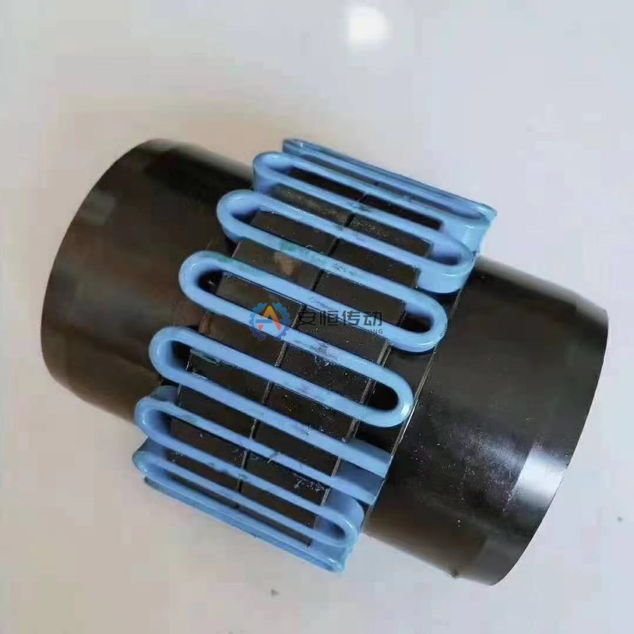
Quick answer: Separate normal crushing torque from impact and jam loads, then verify speed, bores, keyways, alignment, contamination and overload response. A Grid Coupling may be evaluated for torsional cushioning, while a Safety Coupling or Torque Limiter Coupling may be needed when the machine must protect the reducer during a blockage.
1. Describe the crusher duty before choosing a coupling
Record the crusher type, feed material, maximum lump size, normal throughput, drive arrangement, start condition and whether the machine can be started with material in the chamber. Also record feeder behavior, belt or chute blockage, reverse operation, braking and the time between trips. These facts establish whether the coupling is primarily transmitting torque, cushioning torsional shock or protecting a downstream component.
Mining and quarry installations add abrasive dust, water, vibration and difficult access. Note the guard design, lifting space, lubrication route and shutdown window at the same time. A coupling that performs well on a clean test stand may be a poor field choice if seals cannot be inspected or the housing cannot be removed safely.
2. Calculate base torque and identify impact torque
For a shaft carrying power P in kW at speed n in r/min, estimate base torque with T = 9550P / n in N·m. Then identify the events that are not represented by this steady value: material bite, chamber blockage, rotor inertia, direct-on-line starting, reversing and braking. Use drive-current records, protection trips and failure history where available; do not invent a peak value because the application is described as “heavy duty.”
The coupling rating, key, shaft and gearbox must be checked against the same load case. Increasing the coupling size without checking the shaft-end connection can move the failure into the keyway, hub, gearbox or bearings. If the jam must cause a controlled trip, define the trip torque and reset method before selecting a flexible coupling.
3. Decide whether cushioning or disconnect protection is required
A flexible coupling can transmit torque and accommodate specified misalignment. It is not automatically an overload release. A Grid Coupling may be considered when the design objective is to soften torsional shock. A Gear Coupling may be considered when high torque density and controlled misalignment compensation are needed with a maintainable lubrication system.
When a blockage could damage the reducer or shaft, compare a Safety Coupling versus Torque Limiter by protective action: slip, disengage, shear or signal the control system. The required behavior, reset position, sensor interface and residual torque must be written into the RFQ. Do not describe a standard coupling as jam protection unless its design actually provides that function.
4. Check shaft bores, keyways and the installation envelope
Provide both shaft diameters, extension lengths, keyway width and depth, fit, shoulder fillets, hub length, DBSE, maximum outside diameter and removal direction. Crusher vibration can loosen a weak key or expose fretting at the shaft bore. Inspect the old hub for crushed key flanks, reddish wear debris, cracks, scoring and a bore that has been enlarged by previous repairs.
Do not copy worn dimensions into a replacement. Use the old coupling measurement guide and separate as-measured dimensions from design dimensions still requiring confirmation. If the existing flange or shaft interface is non-standard, a Custom Replacement Coupling may reduce installation changes, but the load path still needs engineering review.
5. Control misalignment, vibration and contamination
State cold alignment, expected thermal movement, axial displacement, angular or radial offset and the condition of connected bearings. A crowned tooth profile or flexible element can tolerate a defined range; it cannot compensate for a bent shaft, loose foundation, worn bearing or persistent soft foot. Repeated one-sided wear is evidence to investigate the shaft line before changing the coupling size.
For dust and water, verify seal material, lubricant access, guard clearance and inspection practice. At each planned outage, record temperature, vibration, noise, leakage, fastener witness marks, tooth or element wear and the condition of the lubricant. Use the gear coupling failure troubleshooting sequence when wear is recurring instead of adding grease without identifying the contamination path.
6. Match the coupling to the crusher drive position
A primary crusher motor-to-gearbox connection, a cone crusher drive and a feeder or conveyor drive can have different speed, inertia and protection requirements. The coupling position in the drivetrain must be shown on the drive diagram. Confirm the speed and torque on that shaft section, not only the motor nameplate values.
The mining and crushing application solution is the relevant internal application page for comparing product families. The existing steel-plant crusher article should remain a narrower equipment and steel-industry page, while this article targets mining and quarry buyers who need to define impact and jam response before requesting a replacement.
7. Prepare an RFQ that records the protection decision
Send the crusher model and drive position, motor power, coupling-shaft speed, reducer ratio, start method, normal torque, estimated or recorded impact loads, jam history, shaft drawings, keyways, DBSE, guard dimensions, environment, quantity and required delivery date. Add photos of the failed coupling, shaft ends, keyways, seals and surrounding structure.
State the required action during overload: continue with cushioning, slip within a range, disengage, shear a replaceable element or send a sensor signal to stop the machine. Also state reset method, reset angle, maximum speed, allowable backlash and whether the device must be guarded against setting changes. This gives the supplier a defined engineering question instead of a model-name guess.
Common crusher coupling mistakes
- Applying a generic service factor without recording impact, jam or reversing conditions.
- Choosing a larger coupling while leaving a damaged shaft, key or bearing uncorrected.
- Assuming a flexible coupling will disconnect the drive during a blockage.
- Using a nominal misalignment value without checking the selected size, speed and temperature.
- Omitting dust, water, seal access and the actual removal path from the installation review.
FAQ | Mining Crusher
Is a grid coupling always the best coupling for a crusher?
No. A grid coupling may be suitable when torsional cushioning is required, but the final choice depends on impact loads, speed, shaft interfaces, maintenance access and whether the crusher needs a separate overload-disconnection function.
How should crusher jam protection be specified?
Specify the normal operating and startup loads, the damaging load, the required trip torque, overload duration, slip or disengagement behavior, reset method, sensor requirement and the acceptance test. A product name alone is not a complete protection specification.
What should be photographed for a crusher coupling replacement?
Photograph the installed coupling, both shaft ends, keyways, seals, guard, reducer connection, nameplate and any failed surfaces. Include a scale or measured dimensions for bores, DBSE and the removal clearance.
Need an engineering selection or replacement review?
Send power, speed, shaft diameters, keyway, installation dimensions, drawings or old-part photos. We will review the working condition before confirming the model and quotation.