
Technical Articles
What Is the Difference Between a Safety Coupling and a Torque Limiter? Select by Protective Action
Define the required overload response before debating product names
The distinction between “Safety Coupling” and “Torque Limiter” varies among suppliers. The required protective action is what actually determines selection: should the device slip continuously, disengage immediately, disconnect through a shear element, or trigger a sensor so the control system stops the machine? After the fault is cleared, should it reset automatically, reset at a defined angular position, or require manual element replacement? An RFQ that lists only a product name can lead suppliers to propose entirely different protection strategies.
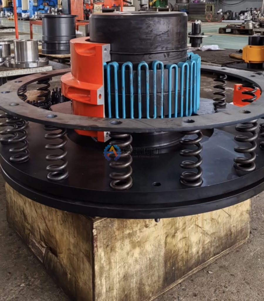
Comparing common protective actions
| Protection method | Response to overload | Best suited to | Risks that must be confirmed |
|---|---|---|---|
| Friction slipping | Relative sliding above the set range | Applications that permit brief slip and need transmitted torque to be limited | Heat from slipping, friction-lining wear, torque drift after reset |
| Ball-detent disengagement | Rapid separation at the trip point | Automated equipment that requires an unambiguous stop signal | Disengagement travel, reset method, repeat-positioning requirements |
| Shear element | A designated component shears during overload | Applications with simple trip logic where downtime for replacement is acceptable | Spare parts, variation between shear elements, fragment containment |
| Synchronous disengagement design | Re-engages at a specified phase after disengagement | Drivetrains with phase or synchronization requirements | Reset angle, backlash, installation orientation |
Accordingly, a Torque Limiter Coupling often emphasizes limiting transmitted torque, while a Safety Coupling often emphasizes abnormal-load disengagement and equipment protection. Final selection must still be based on the design description and trip curve, not the product name alone.
Determining the torque setting
First calculate the base torque under steady operation using `T = 9550P/n`, then obtain the normal startup peak, acceptable process fluctuation, and the hazardous torque level that could damage drivetrain components. The protection setting must be above acceptable normal peaks and below the load limit of the component being protected, with a verifiable separation between the two.
Do not provide only the motor power and ask for the device to be “set at twice that value.” Acceleration inertia, gear ratio, starting under load, braking, changing roll diameter, and material jams all affect peak torque. If records are available from the variable-frequency drive, motor protection relay, or torque sensor, use the timeline to distinguish normal peaks from abnormal events. Without reliable data, the equipment, controls, and coupling engineering teams should jointly define a commissioning plan instead of repeatedly increasing the setting by judgment alone.
Frequent trips are not a reason to raise the setting
Repeated operation of the protection device may result from a seized bearing, material blockage, a change in process cycle, misalignment, friction-surface contamination, or an incorrect setting. Record the load, operating speed, and process status at the time of each trip before correcting the root cause. Raising the setting without investigation can defeat the protection and transfer the failure to the gearbox, shaft, or driven machine.
Select according to equipment consequences, not price
- Where a conveyor may slip briefly after a material jam, a friction Torque Limiter can be evaluated, but account for heat generation and continuous slipping during unattended operation;
- Where a packaging line or assembly machine must stop quickly and signal the PLC, evaluate a disengaging design;
- For winding equipment, account for changes in roll diameter, tension, and rotational inertia so normal process peaks are not mistaken for faults;
- For equipment with a strict phase relationship, specify the reset angle and backlash requirements;
- For equipment with significant personnel-safety risks, determine the guarding and control strategy through the overall machine risk assessment.
A Safety Coupling is only one part of drivetrain protection. It does not replace guards, emergency stops, interlocks, brakes, or an approved mechanical safety design. Conventional Grid Coupling and Gear Coupling designs can cushion or transmit torque, but they generally do not provide an adjustable overload-disconnection function.
Parameters that must be stated in the RFQ
Provide the equipment and process, continuous motor power and operating speed, normal operating torque, basis for the startup peak, required trip torque, overload duration, shaft diameters and keyways at both ends, installation space, connection type, ambient temperature, dust or oil exposure, allowable slip duration, and the required procedure after a trip. Also specify:
- Automatic or manual reset, and whether reset at any angular position is permitted;
- Whether a proximity switch, limit switch, or other signal interface is required;
- Allowable backlash, repeat positioning, and direction of rotation;
- Residual torque after tripping, maximum operating speed, and stopping-distance requirements;
- Whether adjustment must be protected against unauthorized changes, and how the setting will be recorded and verified.
The final technical confirmation should document the protective action, setting range, reset method, interface dimensions, and acceptance test in the drawing or agreement. The purchase then specifies a defined protective behavior instead of an ambiguous product name.
FAQ | What Is the Difference Between a Safety and a Torque Limiter? Select by Protective Action
What is the practical difference between a safety coupling and a torque limiter?
Both protect a drive from overload, but their trip mechanism, residual torque, reset method and repeat-position requirement can differ. The protection action must be stated in the drawing and acceptance test.
What should be confirmed before setting the trip torque?
Confirm normal torque, peak torque, speed, stopping distance, direction, reset access and the consequence of a trip. Do not copy a setting from another machine without checking the actual load path.
Need an engineering selection or replacement review?
Send power, speed, shaft diameters, keyway, installation dimensions, drawings or old-part photos. We will review the working condition before confirming the model and quotation.