Technical Articles
Selecting a Diaphragm Coupling for Pumps and Fans: Operating Speed, Alignment, and Spacer Requirements
Why Diaphragm Couplings Are Often Evaluated for Pumps and Fans
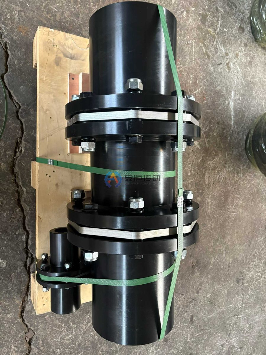
A Diaphragm Coupling transmits torque through metal diaphragm packs and does not rely on lubricated gear teeth. It is well suited to rotating equipment where cleanliness, low maintenance, and shaft-train vibration are important. It can accommodate limited axial displacement, angular misalignment, and radial misalignment, but the diaphragms undergo cyclic stress. Persistent excessive installation misalignment, pipe loads, or axial displacement will shorten fatigue life.
The right question is therefore not “how much error can the diaphragm accommodate?” but “how do the shaft positions change under cold, hot, and varying load conditions, and can the selected design operate within the drawing limits?”
Selection Must Pass Four Checks
1. Torque and Transient Operating Conditions
Estimate basic torque from `T = 9550P/n`. Also specify direct-on-line starting, variable-frequency starting, reverse rotation during shutdown, liquid backflow, fan inertia, and process fluctuations. Adequate rated torque does not mean the diaphragms remain safe under frequent starts and stops or abnormal axial displacement; torque and displacement fatigue must be evaluated together.
2. Operating Speed, Mass Distribution, and Balancing Requirements
At the same torque, higher operating speed increases sensitivity to machining concentricity, assembly, fastener mass consistency, and on-site alignment. The purchaser should provide the maximum continuous operating speed, possible overspeed conditions, and the complete-machine manufacturer's specified balancing requirements. Do not copy a balance grade from unrelated equipment. The balancing scope, operating speed, and acceptance method must be defined during technical confirmation.
3. Shaft Bores, Keyways, and Distance Between Shaft Ends
Provide shaft diameters `d1/d2`, usable shaft-extension lengths, keyways or other connection types, fit requirements, distance between shaft ends (DBSE), and allowable outside diameter. A machinable shaft bore does not necessarily provide adequate hub strength, keyed-connection capacity, or removal clearance. For a custom replacement, measure the shaft ends rather than only the worn hub bores; see How to Measure an Existing Coupling for Replacement.
4. Misalignment and Axial Displacement
Distinguish between initial installation misalignment, thermal displacement during operation, and the equipment's own axial displacement. Pump pipe strain, baseplate soft foot, thermal deformation of the fan housing, and bearing condition can all change hot alignment. All allowable values must follow the final specification drawing; do not use the claim that “a flexible coupling aligns itself” as a substitute for proper alignment.
Choosing a Single-Diaphragm, Double-Diaphragm, or Spacer Design
| Design | Application considerations | Items requiring confirmation |
|---|---|---|
| Single diaphragm | Short distance between shaft ends and limited axial space | Limited radial misalignment capacity and greater sensitivity to installation position |
| Double diaphragm | Combined misalignment capacity is required and sufficient length is available | Spacing between diaphragm packs, axial stiffness, and overall length |
| With spacer | The pump or fan requires spacer removal for maintenance | DBSE, removal direction, spacer mass, and on-site lifting method |
If the mechanical seal must be serviced without moving the motor or pump, determine spacer length from the actual pull-out or maintenance clearance rather than estimating it from the old coupling's overall length. For a longer spacer or higher operating speed, the equipment manufacturer and coupling supplier should also verify shaft-train dynamic characteristics; static torque alone is not sufficient.
What to Check First When Diaphragms Crack Repeatedly
Crack location and direction matter. Cracks near bolt holes may indicate assembly, fastening, or cyclic-displacement issues. A twisted diaphragm pack may indicate an incorrect axial position. If high vibration is also present, investigate imbalance, soft foot, bearings, pipe strain, and process excitation. Before disassembly, mark the diaphragm-pack orientation, bolt positions, and hub clocking at both ends, and retain vibration and temperature trends.
A Diaphragm Coupling is not intended to absorb severe impacts, frequent jams, or persistent misalignment. For low-speed, high-torque applications where lubrication is practical, compare a Gear Coupling. For conveyor or crusher drives requiring torsional damping, see Grid vs. Gear Couplings.
RFQ Data for Technical Confirmation
Submit the equipment type and model, motor power, normal and maximum operating speed, starting method, driver and driven inertia data, shaft diameter and keyway, distance between shaft ends (DBSE), allowable outside diameter, cold- and hot-alignment requirements, axial displacement, spacer requirement, maintenance removal clearance, ambient temperature, and existing vibration or failure records. The supplier's proposal should state the rated torque, allowable speed, overall length, shaft bore, allowable misalignment, fastening requirements, and inspection items so the purchaser can check each point against the complete-machine requirements.
FAQ | Selecting a Diaphragm for Pumps and Fans
What makes a diaphragm coupling suitable for a pump or fan?
A stable high-speed drive, controlled alignment and a shaft arrangement that stays within the diaphragm pack’s axial and angular limits. It should not be selected to mask pipe strain or soft foot.
Why is a diaphragm coupling a poor choice for repeated jams?
Frequent jams and impact reversals can impose transient loads outside the diaphragm pack’s intended duty. Record the event and review a coupling family designed for that load path instead of simply increasing speed rating.
Need an engineering selection or replacement review?
Send power, speed, shaft diameters, keyway, installation dimensions, drawings or old-part photos. We will review the working condition before confirming the model and quotation.