
Technical Articles
Mold Oscillator: Diaphragm Coupling Comparison
A Diaphragm Coupling may be a sensible candidate for Mold Oscillator, but the comparison is not finished until its limits are written down and checked against the station record.
Define the shaft-position duty: Mold Oscillator
Main risks are diaphragm fatigue, installation error, additional vibration load and precision loss from contamination. For Mold Oscillator, record the installed coupling position and verify oscillation stroke, frequency command, phase drift and diaphragm stress against the site record; name the component that must be protected. A diaphragm coupling requires no lubrication and has low backlash, which suits high-speed fans, pumps and drives with balancing requirements.
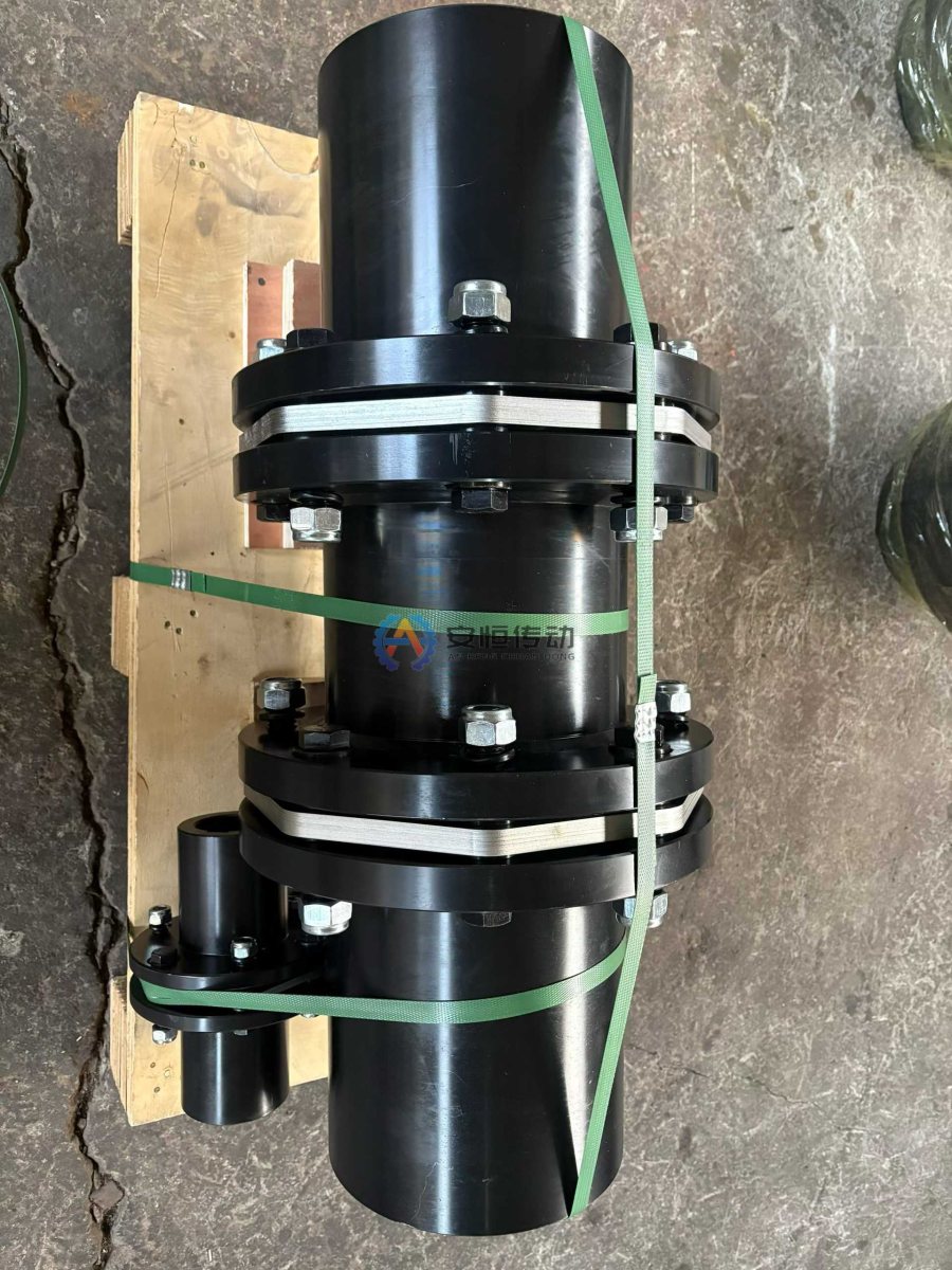
Put backlash, movement and peak load side by side: Mold Oscillator
Confirm oscillation frequency, stroke, drive power, axial movement, allowable backlash and guard space. Relate the event to mechanical linkage, phase drift, diaphragm stress, casting surface, hot alignment and linkage pin when they were involved. Check diaphragm pack arrangement, allowable speed, balancing grade, axial movement and guard clearance. Check the current shaft interface, movement and service route instead of treating a catalogue image as installed evidence.
Name what the candidate cannot solve: Mold Oscillator
Photograph the complete assembly before dismantling and keep the failed component. Compare mold oscillator, oscillation stroke, frequency command, mold table, water spray with the timestamp of the first symptom. If a bore, keyway, guard or seal is worn, preserve the measurement as engineering evidence. Do not use it blindly where radial offset is large, foundation settlement is obvious or installation accuracy is poor. The mold oscillator follows a commanded stroke and frequency rather than a rolling-mill torque cycle. Compare phase drift with the stroke sensor, linkage pin, mechanical stop and mold-level record. Water spray and hot alignment can change diaphragm stress, so the commissioning trace should be kept with the casting-surface observations.
Read the maintenance consequence: Mold Oscillator
For Mold Oscillator, a copied model is only a reference. Release the Diaphragm Coupling after the event, interface, guard and service route are traceable; otherwise return it for site confirmation.
A comparison the RFQ can use: Mold Oscillator
Send the station, coupling position, normal and abnormal load description, speed, shaft measurements, movement, environment, quantity and drawings or photographs. In the field record, name what actually mattered, such as mechanical linkage, phase drift, diaphragm stress, casting surface, hot alignment and linkage pin. Use the relevant product data and recorded loads; do not invent a service factor when the event is unknown.
For Mold Oscillator, after the site data are complete, compare the Diaphragm Coupling product information with the coupling measurement guide and related engineering note.
FAQ for the engineering handover: Mold Oscillator
When should like-for-like replacement stop?
Stop when the old part no longer matches the measured interface, movement, speed or protection requirement.
What should the comparison record show?
Write the duty, evidence, limits and reason for the selected construction, with open data clearly marked.
Need an engineering selection or replacement review?
Send power, speed, shaft diameters, keyway, installation dimensions, drawings or old-part photos. We will review the working condition before confirming the model and quotation.