
Technical Articles
Bucket Wheel Drive Torque Limiter: Mounting Position, Slip Torque and Protection on Stacker-Reclaimers
A bucket wheel that digs into a frozen lump, a buried steel object or a collapsing pile face can stop in a fraction of a second while the motor and drive train try to keep turning. Without a bucket wheel drive torque limiter, that energy goes straight into reducer gears, bearings and shafts. This guide covers where to mount the limiter, how to set its slip torque, and how to make it work with the fluid coupling, current protection and slip sensors on a port stacker-reclaimer.
Where bucket wheel overloads come from
On a stacker-reclaimer the bucket wheel works into a pile that is never uniform. Hard objects, large lumps and frozen crusts give sharp torque spikes, a collapsing pile face can bury the wheel and stall it under load, and material packed between buckets and chute can jam it completely.
The dangerous part of a sudden stop is not the motor’s rated torque but the rotating inertia of the motor and high-speed parts, which keeps driving into the reducer as the wheel stops. That inertia can produce a peak torque far above anything seen in normal digging, which is why a Torque Limiter Coupling that slips at a defined point is used instead of relying on a stronger reducer.
Where to mount the torque limiter: motor side or reducer output
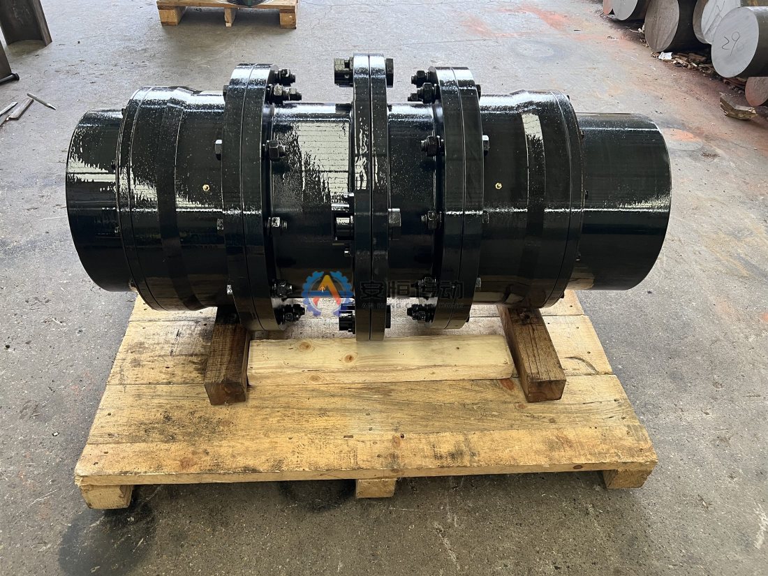
Most bucket wheel drives place the limiter between motor and reducer, often combined with the coupling at that point. Torque there is the reducer output torque divided by the ratio, allowing for efficiency, so the limiter is small and its slip torque is set in that lower range. It also cuts off the motor’s inertia, which is the main source of the peak.
Mounting at the reducer output also protects the reducer against the inertia of its own gears, but the limiter must carry the full wheel torque, so it is much larger, heavier and more expensive, and many wheel drives with shaft-mounted reducers have no room for it. Choose it only when the output layout allows it and the reducer gears themselves need protection from impact.
| Point | Between motor and reducer | At reducer output |
|---|---|---|
| Torque at the limiter | Output torque divided by the ratio | Full wheel torque |
| Limiter size and cost | Small | Large |
| Inertia it cuts off | Motor and high-speed parts | Motor, high-speed parts and reducer gears |
| Layout | Usually easy to fit | Often blocked by shaft-mounted reducers |
Setting the slip torque
The slip torque has to sit in a window: above the peak torque of normal digging, including the breakaway torque needed to start the wheel in the pile, and below the torque the reducer, wheel shaft and connections can safely take. Both limits must be referred to the limiter’s position, so a limiter on the motor side uses values divided by the reducer ratio.
Take the lower limit from the drive’s design data and operating experience: how hard the wheel digs at full capacity in the densest material, and how much torque a normal start under load needs. Take the upper limit from the reducer’s rating for occasional peaks rather than its continuous rated torque, and leave margin for the scatter of a friction limiter’s slip torque.
If that window is narrow, the problem lies in the drive design, not in the limiter setting. Typical scenario: on a reclaimer working a pile with a frozen surface crust, frequent slips on each pass usually call for a slower slewing speed or a shallower cut before any change to the setting; raising the slip torque there just moves the damage back into the reducer.
Working with the fluid coupling, current protection and slip sensors
The torque limiter is one layer of protection, and it works best when the others are set to match. Check each of these against the slip torque:
- Fluid coupling: it softens starts and limits motor torque under slow overloads, but its stall torque in a sudden jam is not a precise limit; set the slip torque so that normal starts through the fluid coupling do not make the limiter slip.
- Motor current protection: it trips on sustained overload after a delay, so it backs up the limiter for stalls but cannot catch a sudden jam. Combine current trends with slip events to judge how often the wheel is really overloaded; current does not read the wheel torque directly.
- Slip detection: a speed sensor that compares input and output speed, interlocked to stop the wheel drive and the slewing motion, so the limiter never slips for long.
A friction limiter that keeps slipping overheats and wears its linings, which lowers the slip torque and invites the next failure. That is why the slip sensor and its interlock matter as much as the limiter itself; for how to separate real blockages from setting errors, see our article on a torque limiter slipping on a screw feeder.
Maintenance in a port environment
Salt spray corrodes exposed springs, adjusting nuts and hub surfaces, and corrosion between friction faces can make a limiter stick after a long idle period, so it slips far above its set value or not at all. Specify protective finishes or corrosion-resistant parts for exposed components; we can supply parts in stainless steel 304 or 316 where the design allows.
Keep water and oil off the friction linings: a damaged guard or a reducer oil leak onto the limiter lowers the slip torque, sometimes sharply. Recheck the slip torque at fixed intervals using the manufacturer’s procedure, check spring setting marks at every inspection, and after long stops consider a controlled slip to break any sticking before full digging resumes.
FAQ
Is a torque limiter better than a shear pin on a bucket wheel?
For a drive that sees repeated overloads, usually yes. A friction torque limiter resets itself after each slip, while a shear pin must be replaced every time; a shear pin only makes sense where overloads are rare and a stop for replacement is acceptable.
Can the fluid coupling replace the torque limiter?
No. A fluid coupling limits torque only to its own stall characteristic, which can still be above what the reducer should see in a sudden jam, and it cannot be set to a precise release point. The two work together: the fluid coupling for starts and slow overloads, the limiter for sudden peaks.
How do we know the slip torque is still correct?
Recheck it at the intervals the manufacturer recommends and after any slip event with heat marks, oil contamination or a long idle period. Compare slip events with operating conditions; a limiter that suddenly slips more or less often than before needs checking.
Choose the mounting position from your drive layout, set the slip torque inside the window between digging peaks and reducer limits, and tie the limiter into slip detection and the drive controls. We check torque, speed, shaft diameter, keyway, service factor, misalignment and the working environment before picking a size; standard sizes ship in as little as 10 days and copies made from an old part take from 20 days, and a material certificate (mill test certificate) and dimensional inspection report can be supplied with the shipment. Send us your drawing with motor, reducer and bucket wheel data, and we will propose a torque limiter coupling and slip torque setting for your bucket wheel drive.
Need an engineering selection or replacement review?
Send power, speed, shaft diameters, keyway, installation dimensions, drawings or old-part photos. We will review the working condition before confirming the model and quotation.