
Technical Articles
Coupling Axial and Angular Misalignment: Limits, Symptoms, and Checks
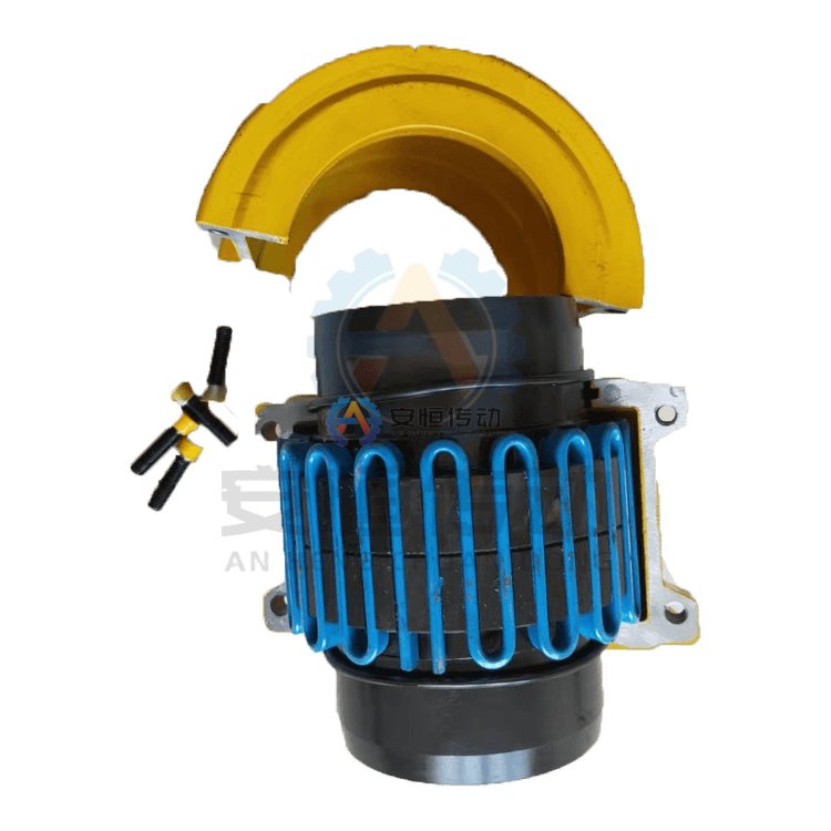
Axial displacement is movement along the shaft line; angular misalignment is a change in the angle between shaft centerlines. A coupling may accommodate one while being sensitive to the other. Selection and alignment must therefore use separate measurements and separate allowable limits.
Separate axial travel from angular error
Thermal growth, bearing movement, roll adjustment, pump thrust, and foundation settlement can change axial position. Angular error may come from soft foot, tilted bases, pipe strain, or a gearbox that is not level. The symptoms overlap, but the corrective actions do not.
Open engineering data for Coupling Axial and Angular Misalignment
Measure axial position at operating temperature where practical, and record angular and parallel offset independently. Confirm the coupling's axial float, angular capacity, radial load, speed, bore, keyway, and seal movement. Check whether the coupling is intended to locate or float the shaft.
For axial and angular misalignment, start with the Gear Coupling page. Use the custom replacement coupling page when the installed interface is no longer catalogue standard.
| Engineering input | Confirmation required |
|---|---|
| Load cycle | Continuous, start-up, reversing and blocked-load torque |
| Speed and movement | Normal speed, axial displacement and angular misalignment |
| Interface | Bore, keyway, hub length, DBSE and guard envelope |
| Environment | Temperature, dust, moisture, lubricant or elastomer exposure |
Separate the machine fault from coupling damage: Coupling Axial and Angular Misalignment
Use the larger actual movement plus an engineering margin, not a nominal alignment number. Check reaction forces and bearing loads when angular misalignment is present. A coupling that permits movement may still transmit harmful forces if it is operated near its limit.
For axial and angular misalignment, the coupling misalignment prevention guide is useful when the failure history suggests that the rating basis or transient load has been misunderstood.
Prove the repair on the next run: Coupling Axial and Angular Misalignment
Correct soft foot and pipe strain before final alignment. Set the axial reference, rotate the shafts, and take readings at more than one angular position. After a thermal run, repeat the check and compare the as-found values with the coupling drawing.
Keep the failed part and its measurements: Coupling Axial and Angular Misalignment
One-sided tooth or element wear, hot bearings, seal extrusion, and repeated bolt loosening can identify movement. If the symptom changes with temperature, investigate thermal growth. If it changes with load, investigate torque and bearing movement.
On an axial and angular misalignment installation, do not replace the worn part before checking the shaft, keyway, bearings, guard and machine alignment. Read the damage as evidence, then check the surrounding machine before choosing the part.
Diagnosis handover for this station: Coupling Axial and Angular Misalignment
Send cold and hot alignment readings, shaft drawings, DBSE, expected thermal growth, speed, torque, bore, keyway, photos, and quantity. Ask the supplier to identify which movement is accommodated and which must be corrected.
Two practical questions: Coupling Axial and Angular Misalignment
Can a coupling symptom prove the root cause?
No. Check the machine event, shaft, key, bearings, foundation, guard and alignment before assigning the cause to the coupling.
What should be repeated after repair?
Repeat the measurement or operating check that first exposed the problem, under a comparable load, and keep the result with the failure record.
Send a reviewable engineering request: Coupling Axial and Angular Misalignment
For the “Coupling Axial and Angular Misalignment” review, send the equipment name, operating duty, available torque and speed data, shaft drawing or clear photos, quantity and delivery need through technical RFQ form. Keep measured values separate from estimates so the drawing review can see what is still open.
Need an engineering selection or replacement review?
Send power, speed, shaft diameters, keyway, installation dimensions, drawings or old-part photos. We will review the working condition before confirming the model and quotation.