
Technical Articles
Caster Segment Drive Cardan Shafts: Offline Inspection, Lubrication and Spare Planning for the Annual Overhaul
Cardan shafts on caster segment drives rarely fail from torque alone. Spray water, steam and scale get into the cross bearings and the telescoping spline, the grease washes out, and the spline stops sliding when the roll gap changes. The segment's time in the maintenance shop is the best chance to catch this, and the spares need to be in stock before the annual overhaul starts.
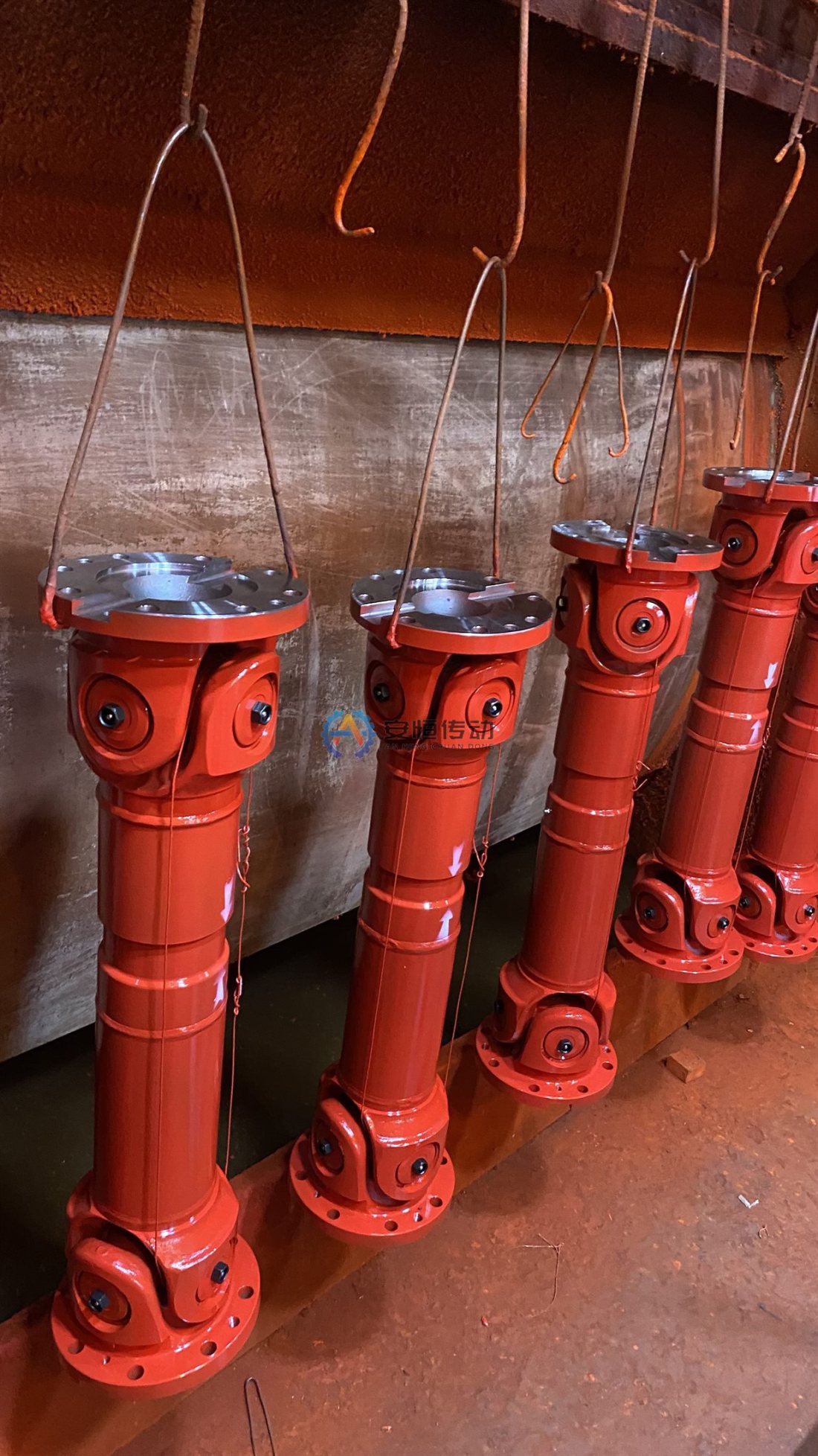
Why Secondary Cooling Is Hard on Segment Drive Shafts
In the secondary cooling zone the shaft sits in spray water, steam and fine iron oxide scale, with radiant heat from the strand. Water that passes a cross seal displaces the grease and corrodes the needle rollers and trunnions. Scale that reaches the spline acts like grinding paste on the tooth flanks.
In a universal joint the needle rollers do not spin; they rock back and forth through an arc set by the working angle. Segment drives usually run at small angles, low speed and high torque, so the rollers barely move, the grease film is not renewed, and brinelling marks can form on the trunnions.
The shaft sees its peak torque when the strand is restarted after a stop or when a roll sticks. At low speed, damage builds up quietly until a bearing cup cracks or the spline seizes. A seized spline then pushes axial force into the roll bearings and the gearbox every time the driven roll moves with a roll gap change.
Offline Inspection: Cross, Needle Bearings, Spline and Flanges
Before dismantling, find the match marks on the spline and yokes and renew them if they are faint. Record the findings against the shaft position so that one overhaul can be compared with the next.
- Cross and needle bearings: Turn each joint by hand and feel for notches or tight spots. Compare the play with the manufacturer's limit or a new part; brown, milky or watery grease at the seals usually means water has been in.
- Trunnions: Light brinelling marks are an early warning. Rust pitting or spalling means the cross assembly is finished.
- Telescoping spline: Slide it through the full stroke; it should move evenly without stick-slip. Check the flanks for wear steps, compare torsional backlash with a new part, and check the boot or seal for tears and packed scale.
- Flanges, spigots and bolts: Check flange faces and centering spigots for fretting and impact damage, and check bolts for stretch and damaged threads. Do not reuse bolts that have been overloaded.
Typical scenario: a segment from the straightening zone arrives in the shop, its drive shaft only collapses when pulled by the crane, and the grease at one cross is brown and watery. That combination usually means the spline seal and at least one cross seal failed together, so repair both rather than only freeing the spline.
A spline with flank wear but no step can usually go back into service with new seals. A cross with pitted trunnions is replaced as a complete assembly.
Lubrication and Seals: Water Resistance Without Blowing Out the Seals
Set the regreasing interval from your own inspection records, not only from the shaft drawing. Positions under heavier spray or closer to the strand usually need shorter intervals, and every segment that comes offline should be regreased.
Choose a grease with good water washout resistance and adhesion, such as a lithium complex or calcium sulfonate type with EP additives, and check that it is compatible with the grease already in the joints. Incompatible thickeners can soften and run out, so when you change grease type, purge the old grease completely instead of topping up.
Pressure is where seals are lost. Use a hand grease gun rather than a high-pressure pneumatic gun, which can turn a seal lip over, and stop as soon as clean grease appears at every bearing seal on the cross. If one bearing will not purge, clear the blocked passage instead of raising the pressure. On the spline, keep the vent open so that trapped grease cannot hydraulically lock the telescoping travel.
After Refitting: Phase, Installed Length and Working Angle
Most refit problems come down to phase, installed length and joint angles. Check them before the first heat, not after the first complaint.
- Phase: The yokes on the intermediate shaft must line up with the match marks. A spline assembled out of its marked position gives uneven roll speed and a cyclic torque fluctuation.
- Installed length: Check the spline with the roll gap at both ends of its range. It must not bottom out at the shortest position and must keep the minimum engagement specified for the shaft at the longest.
- Working angles: The angles at both joints should be equal so that the speed fluctuation cancels out. If the shaft runs almost straight for long periods, check its joints first for brinelling at the next overhaul.
- Bolting: Tighten flange bolts crosswise to the specified tightening torque, with new locking elements where the design requires them.
Then jog the drive and watch the shaft through a full revolution; fix any binding, knocking or spline jumping now. For angle limits and site checks, see our universal joint working angle checklist.
Planning Spares for the Annual Overhaul
Size the spare list from your own records: the number of driven positions, the positions that failed in recent campaigns, and how many shafts the shop can rebuild during the shutdown. Positions with repeated water damage deserve a complete spare shaft, so they can be swapped instead of repaired under time pressure.
| Spare item | Main use | How to size the quantity |
|---|---|---|
| Complete cardan shaft | Swap during the shutdown | Repeat-failure positions, plus a reserve for unexpected findings |
| Cross assembly | Shop rebuild of shafts with good yokes and spline | Crosses scrapped in recent overhauls |
| Seal kits and spline boots | Every rebuild, and every damaged seal found during regreasing | A set for each joint you plan to open, plus a reserve |
| Flange bolts and locking elements | Every disconnected flange | Full sets per shaft, since overloaded bolts are not reused |
Fewer variants mean fewer spares. If several positions use shafts with the same flange and torque class but different lengths, ask whether one length range can cover them.
Order early. Our Universal Joint Coupling SWC range runs from SWC100 to SWC620 in 14 sizes, with rated torque Tn from 1.25 to 1000 kN·m across the table. Standard sizes take 15–25 days, while non-standard or large shafts get a confirmed lead time after drawing review, so send drawings as soon as the shutdown date is fixed.
Spares often wait in the store for some time. Our standard packing is a black oxide finish and rust-preventive oil, with the shaft wrapped in plastic film and packed in an export wooden case; even so, check the oil film again before fitting a shaft that has been stored for a long time.
FAQ
Can we replace only the cross assembly instead of the whole shaft?
Yes, if the yoke bores are not worn or out of round, the flanges and spigots are undamaged and the spline still slides evenly. If the yoke bores are worn, a new cross will not stay tight for long, and a complete shaft is the better choice.
How do we tell whether water enters through the cross seals or the spline seal?
Look at where the bad grease is. Watery grease at the cross seals points to the cross seals; rust and scale between the spline teeth with clean grease at the crosses points to the spline boot or seal. Combine this with the shaft's position and the local spray pattern to decide which seal to upgrade.
What data do you need to quote a replacement segment drive shaft?
A drawing is best. Without one, send the compressed length, telescoping stroke, flange diameter, bolt circle and hole details, spigot size, working angle, torque and speed, plus photos of the nameplate, both flanges and the spline. We can build a replacement Universal Joint Coupling from a drawing or from photos and measured dimensions of the old shaft.
What materials are used, and which documents can come with the shafts?
Typical materials are C45 (≈ AISI 1045) and 42CrMo4 (≈ AISI 4140), or the grade your project specifies; heat treatment such as quenching and tempering or induction hardening follows the model and the drawing. On request we supply a material certificate (mill test certificate), dimensional inspection report, dynamic balancing report, heat treatment report and ultrasonic testing (UT) report, with the inspection items confirmed before the order.
If your caster overhaul is already on the calendar, send us drawings, or photos and measurements, for the positions you want to stock, together with the planned shutdown date. We will confirm sizes, documents and lead time against that date. Send us your drawing
Need an engineering selection or replacement review?
Send power, speed, shaft diameters, keyway, installation dimensions, drawings or old-part photos. We will review the working condition before confirming the model and quotation.