
Technical Articles
Grid Coupling Spring Failure on Ball Mill Drives: Frozen-Charge Shock, Lubrication or Misalignment?
When a grid spring breaks on a ball mill main drive, fitting a new grid is quick, and that is exactly why the same failure keeps coming back. The broken grid, the hub grooves and the grease inside the cover usually show whether the cause is a frozen-charge start, lubrication failure or misalignment. Here is how to read those clues and when the coupling itself needs re-sizing.
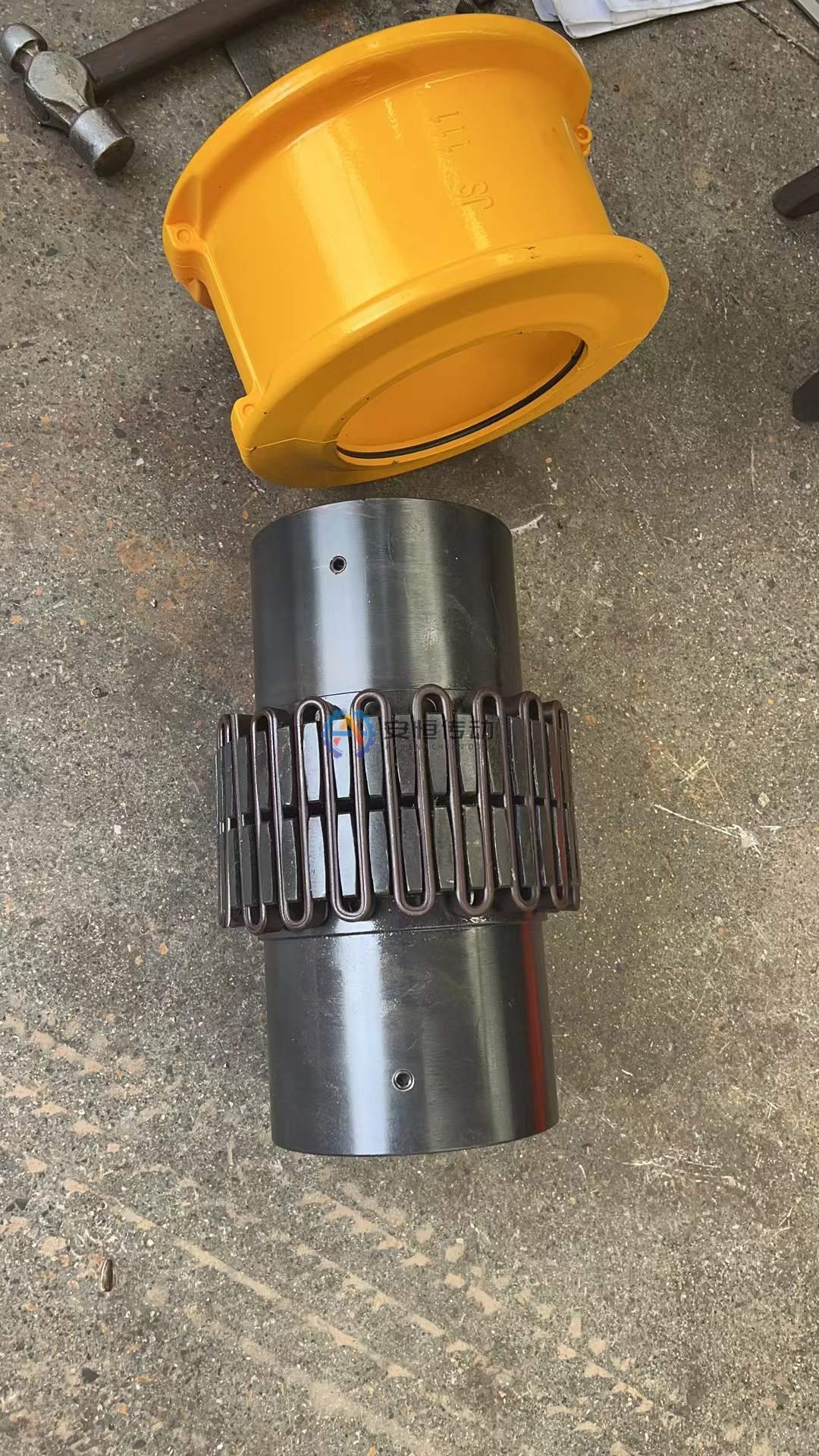
Why ball mill drives are hard on grid couplings
A ball mill is one of the toughest duties a Grid Coupling can face. The shell, liners, grinding media and charge add up to a very large rotating inertia, and the drive must start that mass under load, so every start pushes the coupling through a breakaway torque well above running torque.
Two conditions make it worse. After a long stop the charge can compact into a frozen charge that lifts as a solid block instead of cascading, and when it drops, the impact travels back through the pinion, gearbox and coupling. If inching torque passes through the coupling, rocking the mill back and forth also makes the grid knock against both flanks of the hub teeth.
Read the broken grid and the grooves first
Before scrapping the old grid, lay the pieces out in order and photograph the fracture faces, hub teeth and grease. Several rungs snapped at once tell a different story from a single break with cracks in the neighbouring rungs.
A fatigue fracture is flat and fairly smooth, often with beach marks spreading from one origin at the surface, typically at the loop or where the grid contacts the tooth edge. An overload fracture is rough and granular, without beach marks, and nearby rungs are often bent or permanently deformed. If a fatigue crack started at a worn notch or a corrosion pit, treat it as a lubrication or sealing problem first, not a sizing problem.
| What you find | Most likely cause |
|---|---|
| Several rungs broken at once, rough faces, bent rungs | Overload: frozen-charge start or another single shock |
| Smooth faces with beach marks, cracked neighbouring rungs, little wear | Fatigue: repeated start-up peaks or too little torque margin |
| Grid worn thin at contact points, stepped groove wear, dry grease, reddish-brown powder | Lubrication failure and fretting wear |
| Wear at one end of the teeth, or uneven wear between the two hubs | Misalignment or wrong hub gap |
Field data supports the diagnosis but does not replace it. Combine the start-up current trend, bearing temperatures and vibration readings with what you see on the parts; none of them reads the torque on the grid directly.
Frozen charge and start-up shock
If the fracture says overload, check the stop history first: a long stop with slurry left in the mill is the classic setup for a frozen charge. Before restarting, turn the mill with the inching drive and confirm the charge breaks loose and cascades; if it does not, keep inching back and forth to loosen it. Disengage the inching drive fully before the main motor starts. Grinding out or draining slurry before a planned stop, where the process allows, leaves less material to set.
The start method matters too. A direct-on-line start gives a sharp torque spike, while an air clutch, soft starter or variable-frequency drive limits how quickly torque builds. If the drive has a clutch or torque limiter, compare its slip torque or release torque with the coupling’s allowable peak torque; if the protection is set higher than the coupling can take, the grid becomes the fuse.
Lubrication and seals
A grid coupling needs grease so the grid can slide in the grooves as it flexes. When the grease dries out, washes out or leaks away, grid and teeth wear notches into each other, and those notches become fatigue crack origins.
Around a ball mill the cover sits in a wet, dusty area with slurry splashes and wash-down water. At every inspection, check the cover gaskets, seals, bolts and plugs, and treat any grease streak on the cover as a seal failure. Water or slurry inside the cover turns grease into an abrasive paste.
Use a grease made for couplings that resists separating under centrifugal force; general-purpose bearing grease tends to separate in a spinning cover. Treat the manufacturer’s regreasing interval as a maximum and shorten it for hot running, frequent starts or wet areas. When you regrease, check the old grease that comes out first.
Alignment, foundation and thermal growth
Grid couplings accept some misalignment, but running near the limit makes the grid slide in the grooves every revolution, which speeds up wear and fatigue. Ball mill foundations settle, and the motor, gearbox and pinion often sit on separate blocks. If alignment drifts again after correction, check soft foot, anchor bolts and grout before blaming the coupling.
The motor and gearbox grow by different amounts as they warm up, so set cold offsets for the expected thermal growth and verify alignment hot after a full run. On large sleeve-bearing motors, confirm the rotor runs at its magnetic center and the hub gap matches the coupling specification; otherwise axial movement can push the hubs together and pinch the grid.
When to re-size for the actual peak torque
Re-size when the evidence points to the coupling itself: fatigue fractures return after lubrication and alignment are fixed, or overload fractures continue even though frozen-charge starts are handled properly. Either way, the coupling is seeing peak torque higher or more often than its size allows.
For the re-check, collect the motor rated torque and starting characteristics, start method, any slip torque setting, number of starts, frequency of frozen-charge events, and shaft diameters and keyways. We size against the real peak torque with a suitable service factor, also checking speed, misalignment and the working environment, not against running torque alone.
Our JS series runs from JS1 to JS25, with bores from 18 to 500 mm across the range; torque and speed limits depend on the size. A correctly sized grid coupling suits mills where shock is the main problem, because the grid flexes and absorbs part of each impact. If the shafts push you to the top of the range, or the drive needs torque density more than shock damping, a gear coupling may fit better; see Grid or Gear Couplings for Crushers and Conveyors?.
FAQ
Can I replace only the grid and keep the old hubs?
Only if the hub teeth are still in good shape. Stepped wear, peening or cracks in the grooves will wear out a new grid faster than the first one, so replace the hubs as well when the tooth profile is visibly worn.
Does a fatigue fracture always mean the coupling is undersized?
No. Fatigue starting at a wear notch usually points to lubrication or seals, and fatigue alongside one-sided tooth wear points to alignment. Only when both are confirmed good does repeated fatigue suggest the size is too small for the real load cycle.
How do I confirm a frozen charge caused the break?
Match the overload features on the grid with the operating log: a start after a long stop, a start without inching first, or a trip right after start. Combined with the parts and the operators’ account, the start-up current trace is a useful clue, but not proof on its own.
If your mill keeps breaking grids, read the fracture and the grease first, fix what the evidence points to, and only then decide on size. Lead time for standard models is 15–25 days, and a material certificate (mill test certificate) and ultrasonic testing (UT) report can be supplied with the shipment. Send us your drawing, or photos of the old coupling with measured dimensions and your operating data, and we will check the size against your actual peak torque.
Need an engineering selection or replacement review?
Send power, speed, shaft diameters, keyway, installation dimensions, drawings or old-part photos. We will review the working condition before confirming the model and quotation.