
Technical Articles
Grid Coupling Maintenance Checklist for Paper Machine Auxiliary Drives: Grid, Grease and Cover
Planned shutdowns on a paper machine, such as felt or wire changes, are the natural window to open each Grid Coupling on the auxiliary drives before it fails. A grid coupling maintenance checklist turns that window into a consistent routine: what to look at, in what order, what counts as an early warning, and when to order spares. This guide is written for pumps, fans, agitators and other auxiliary drives in the wet, warm conditions of a paper mill.
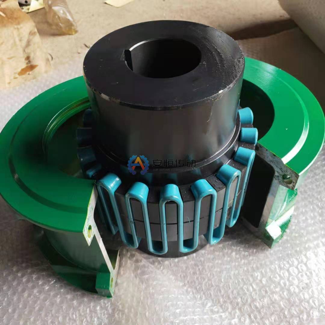
Before you open the cover: isolation and a first look
Lock out and tag the drive, confirm it cannot rotate, and make sure connected equipment, such as a pump with a standing column of liquid, cannot drive the coupling backwards. Clean the outside of the cover first, so pulp fibre and dirt do not fall into the coupling when it is opened.
Before removing anything, look for grease streaks at the cover joint and seals, missing or loose plugs and bolts, and signs of rubbing on the guard. Note them on the record sheet; a leak found now explains much of what you will see inside. Mark the cover halves and their orientation so they go back the same way.
Inspection order once the cover is off
Work from the outside in, so each step tells you something before the evidence is disturbed. Check in this order:
- Seals and gaskets: hardened, cut, flattened or missing lips and gasket sections.
- Grease condition before wiping: colour, consistency, water, fibre, rust particles and whether oil has separated from the thickener.
- Grid: after removing grease, look along its full length for cracks, especially at the loops, and for rungs that are bent or not fully seated.
- Hub teeth: contact marks, wear steps and whether wear is even across the tooth width.
- Hub gap and alignment, if readings or the wear pattern suggest movement.
Photograph each stage with a reference, such as the cover mark, in the picture. If vibration or noise readings rose before the shutdown, combine them with what you find here; they are clues that point to where to look, not a diagnosis on their own.
What early problems look like
Most grid failures announce themselves well before a grid breaks. These are the signs worth acting on at a planned stop:
| What you see | What it usually means | Action |
|---|---|---|
| Hairline crack at a grid loop | Fatigue has started | Replace the grid now |
| Rungs bent or grid permanently set | Overload or peak torque at starts | Replace the grid and check the load history |
| Wear concentrated at one end of the teeth or grid | Misalignment | Realign and check hub gap |
| Grid worn thin at contact points, stepped tooth wear | Lubrication failure | Replace worn parts, fix seals, shorten the interval |
| Hub gap outside specification | Axial movement or wrong assembly | Reset the gap and find the cause |
| Dry, caked, milky or fibre-laden grease | Grease loss, water ingress or contamination | Clean out, regrease, renew seals |
Typical scenario: on a vacuum pump drive near the wet end, wash-down water gets past a worn cover gasket, and at the next shutdown the grease comes out milky. The grid still looks fine, but the gasket and the regreasing interval need attention now, before rust and wear notches start a fatigue crack.
Regreasing and reassembly
Remove the old grease completely rather than topping up, so contaminated grease is not mixed with new. Use a grease suited to grid couplings, one that resists separating under centrifugal force and holds up in damp conditions, and check that it is compatible with what was used before; mixing incompatible greases can make the mixture softer or harder.
Pack the grooves with grease, refit the grid so every rung sits fully in its groove, tapping it home with a soft mallet, and fit a segmented grid in the order and direction the manual shows. Renew damaged seals and gaskets, refit the cover halves to their marks, and tighten the cover bolts evenly to the specified torque.
Fill through the plugs until grease appears at the opposite plug, then refit and tighten the plugs. If the motor or driven machine was moved, check hub gap and alignment before closing up, and record the final readings.
Setting the inspection interval and keeping records
There is no single correct interval for every drive. Start from the coupling manufacturer’s recommendation and shorten it for frequent starts and stops, strongly fluctuating load, wet or steamy surroundings and wash-down areas; lengthen it only when several records in a row show clean grease, intact seals and no new wear.
A record sheet is what makes those decisions possible. Keep these fields for every coupling:
- Equipment tag, coupling size and cover type.
- Date, and operating hours or starts since the last inspection.
- Seal, grease, grid and hub tooth condition, with photo references.
- Hub gap and alignment readings, actions taken and parts replaced.
- Spares used and the next planned inspection.
FAQ
When should we replace the whole coupling instead of just the grid?
When hub teeth show stepped wear, cracks or a worn profile, or the hubs are loose on the shafts. A new grid in worn grooves wears out quickly, so replace the hubs too; if failures keep coming back despite good maintenance, compare the coupling type with the duty, for example in our article on grid or gear couplings.
Which spares should be kept for a planned shutdown?
For each coupling size in use, at least one grid, a full set of seals and gaskets, and cover bolts, plus a cover where covers get damaged in handling. Order with the coupling size, cover type and, for hubs, bore and keyway dimensions; our JS series runs from JS1 to JS25 with bores from 18 to 500 mm across the range.
Can grease leaks be fixed without opening the coupling?
Tightening a loose plug or cover bolt may stop a minor leak, but a leaking seal or gasket needs the cover open. Left alone, it lets water and fibre in and grease out, which is how most grid failures begin.
Use each planned shutdown to work through the grid coupling maintenance checklist, record what you find, and order spares before the next stop rather than during it. We make replacement grid couplings from drawings or from photos and measured dimensions; standard sizes ship in as little as 10 days and copies made from an old part take from 20 days, and a material certificate (mill test certificate) and dimensional inspection report can be supplied with the shipment. Send us your drawing or the coupling size and photos, and we will confirm the parts you need.
Need an engineering selection or replacement review?
Send power, speed, shaft diameters, keyway, installation dimensions, drawings or old-part photos. We will review the working condition before confirming the model and quotation.