
Technical Articles
Apron Feeder Coupling Failure: Crushed Gear Teeth, Keyway Cracks and Shock Loads
On an apron feeder under a truck dump, the low-speed coupling between reducer and head shaft carries the full feeder torque, and every truckload reaches it in some form. When crushed teeth or cracked keyways keep returning at the same position, a new hub of the same size usually fails the same way. The cause sits on the load side or the installation side, and the failed parts show where to look first.
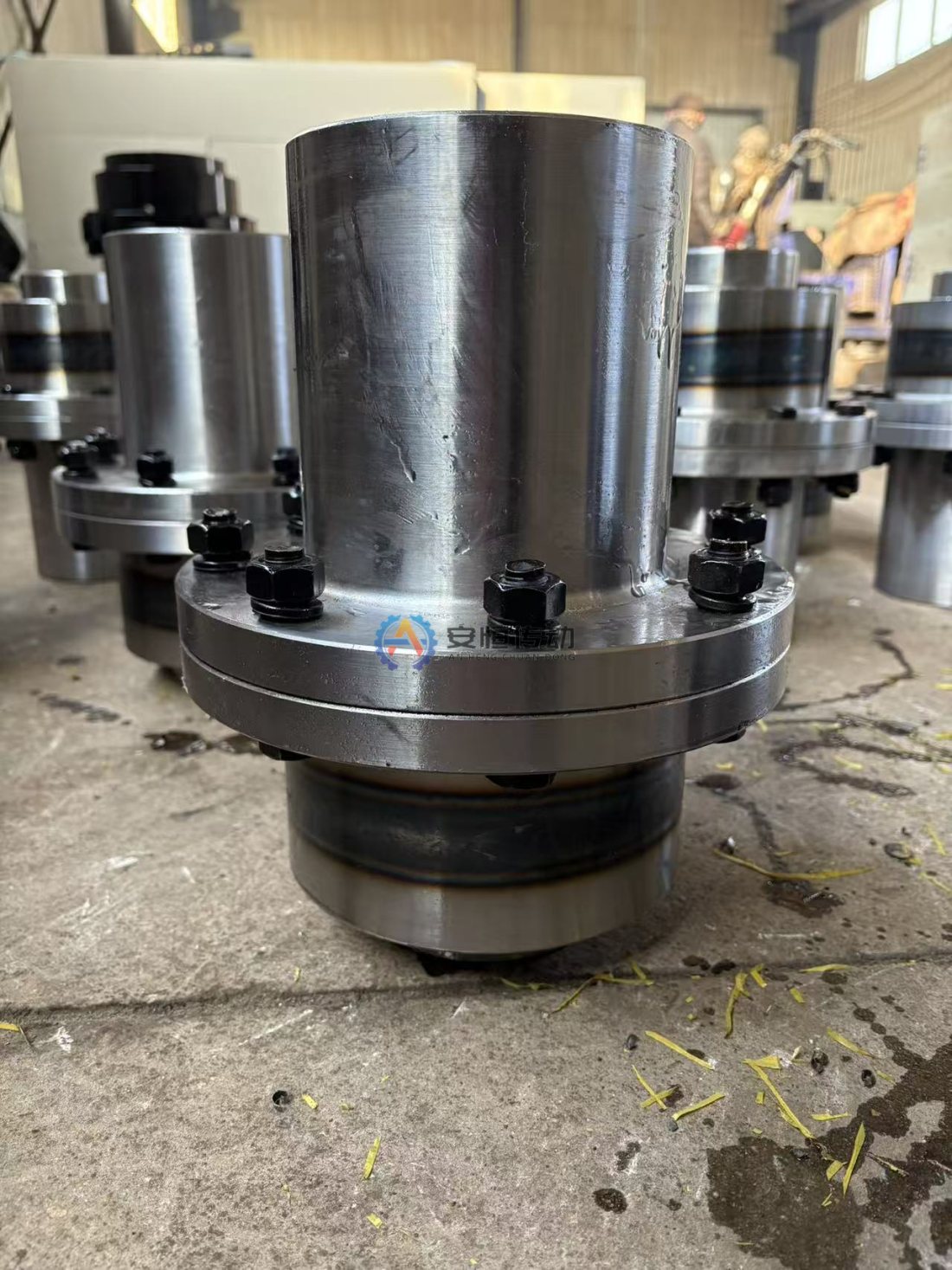
Why the low-speed coupling on an apron feeder takes a beating
An apron feeder moves a heavy bed of ore at very low speed, so the reducer turns motor torque into a very large torque at the head shaft. A Gear Coupling is the usual choice there because it carries high torque in a compact size and accepts some misalignment between reducer output and head shaft.
Several things push that coupling far above running torque. Rocks dumped from trucks hit the pans and the shock travels through the chain and head sprocket, starts under a full hopper need a high breakaway torque, and oversize rocks wedged between skirts and pans can stall the drive. A gear coupling is torsionally stiff, so it passes these peaks straight to teeth, keys and hubs instead of absorbing them.
Read the failure before ordering parts
Clean the hubs and sleeve, mark their positions, and inspect teeth, bores and keyways before anything is scrapped. Note whether damage sits on one flank or both, across the full face width or at the tooth ends, and on the reducer-side hub, the head-shaft-side hub or both.
| What you find | Points mainly to |
|---|---|
| Flanks flattened or dented, metal rolled toward the tips | Peak torque from impact, stalls or hard starts |
| Fine pitting spread over the flanks | Repeated high contact stress, often with poor lubrication |
| Crushing or pitting concentrated at the tooth ends | Misalignment, only part of the face width carrying load |
| Crack at a tooth root, sometimes with beach marks | Bending overload or fatigue from repeated peaks |
| Crack running from a keyway corner into the hub | Torque peaks plus a small corner radius, excess interference or a loose key |
| Reddish-brown powder and polished bands in the bore | Fretting from a loose bore fit or a loose key |
Damage on both flanks points to reversing loads, from drive reversals or rebound after impacts, while one-flank damage follows the normal driving direction. For tooth patterns in more detail, see our tooth wear inspection guide.
Load-side causes: dumping impact, full-hopper starts and drive settings
Never let the hopper run empty between trucks. A bed of ore on the pans cushions the next load; when trucks dump onto bare pans, the impact goes straight into chain, sprocket and coupling, and a high drop makes it worse. Check that the hopper and any impact protection still work as designed.
Starting under a full hopper is normal duty, but compacted, wet or sticky ore after a long stop can raise breakaway torque well above a normal start, and oversize rocks jammed at the skirt plates or discharge lip do the same. If stalls repeat, look at the skirt gap and the discharge area, not just the coupling.
Drive settings decide how much of the motor’s peak torque reaches the coupling. A variable-frequency drive with a very short acceleration ramp or a high torque limit, or repeated reversing to free a jam, hammers teeth and keys. Combine drive current trends at start and during stalls with what you see on the parts; they are clues, not a reading of coupling torque.
Installation-side causes: alignment, bore fit and base bolts
A gear coupling accepts some misalignment, but running near its limit shifts load toward the tooth ends, where contact area is smallest and crushing starts first. Check alignment between reducer output and head shaft, loaded as well as empty if you can, because the frame and head shaft bearings can shift under load.
The bore and key carry torque into the hub, so their fit matters as much as tooth size. A loose bore fit leaves the key to carry shocks alone; the key works loose, the bore frets and cracks start at the keyway. Excess interference is no cure either, since hoop stress plus torque at a sharp keyway corner is a classic crack origin: follow the fit on the drawing, use a proper corner radius, and make sure the key fits tightly on its sides over its full length. See our fretting and loose-key guide for the bore side.
Shocks loosen reducer base bolts and crack grout over time, and a reducer that rocks on its base turns every truckload into misalignment. Check anchor bolt torque and grout condition at every coupling inspection, not only after a failure.
Fixes: service factor, coupling size and overload protection
Re-check the service factor against the real duty: dumping impact, full-hopper starts, stalls on oversize and reversing. If the original selection used motor rated torque with a light-duty factor, the coupling has been running with less margin than the drawing suggests.
A larger coupling helps when overload persists after the load-side and installation-side causes are fixed, because it adds tooth contact area and hub wall around the keyway. Our CL series (CL1–CL19) and CLZ series (CLZ1–CLZ19) cover bores from 18 to 560 mm across the range, with torque and speed limits depending on size, and before picking a size we check torque, speed, shaft diameter, keyway, service factor, misalignment and the working environment. Hubs and sleeves can be made in 42CrMo4 (≈ AISI 4140) with quenching and tempering, plus induction hardening where the drawing calls for it.
A bigger gear coupling does not absorb shock; it only carries more of it. If dumping impact or stalls cannot be controlled at the hopper, add overload protection, such as a torque limiter whose slip torque or release torque sits above the breakaway torque the feeder needs but below the coupling’s allowable peak torque, or a drive torque limit set in the same window. Otherwise a stronger coupling just moves the next failure to the key, the head shaft or the reducer.
FAQ
Can a cracked hub be welded and reused?
No. A crack from a keyway corner keeps growing under the same torque peaks, and welding a heat-treated hub changes the material around the repair. Replace the hub and check the mating hub and the shaft keyway for cracks while the coupling is apart.
Why does the same hub always fail first?
Usually that hub has the thinner wall around its keyway, the looser bore fit or the larger share of misalignment. Compare bore sizes, fit records and alignment readings for both hubs.
Does pitting mean the coupling is undersized?
Not by itself. Pitting spread over the flanks together with dry or degraded grease points first to lubrication, so check grease and seals before resizing. Crushing that returns after lubrication, alignment and fits are corrected is the stronger sign that peak torque exceeds the size.
If crushed teeth or keyway cracks keep returning on your feeder, keep a material bed in the hopper, fix alignment and fits, and then re-check size and protection against the real peak torque. We make replacement couplings from drawings or from photos and measured dimensions; standard sizes ship in as little as 10 days and copies made from an old part take from 20 days, and a material certificate (mill test certificate) and ultrasonic testing (UT) report can be supplied with the shipment. Send us your drawing with motor, reducer and feeder data, and we will check the size against your duty.
Need an engineering selection or replacement review?
Send power, speed, shaft diameters, keyway, installation dimensions, drawings or old-part photos. We will review the working condition before confirming the model and quotation.