
Technical Articles
Kiln Drive Coupling Replacement Without Drawings: Measuring the Old Part Before the Annual Shutdown
A rotary kiln’s main drive coupling usually gets replaced during the annual shutdown, and on older kilns the original coupling drawing has often been lost. Measure one dimension wrong and the new part will not go on, with the kiln waiting and the window closing. Here is how to split the work between what can be measured before the stop and what must wait until the old coupling comes off, and how to plan so the new part arrives in time.
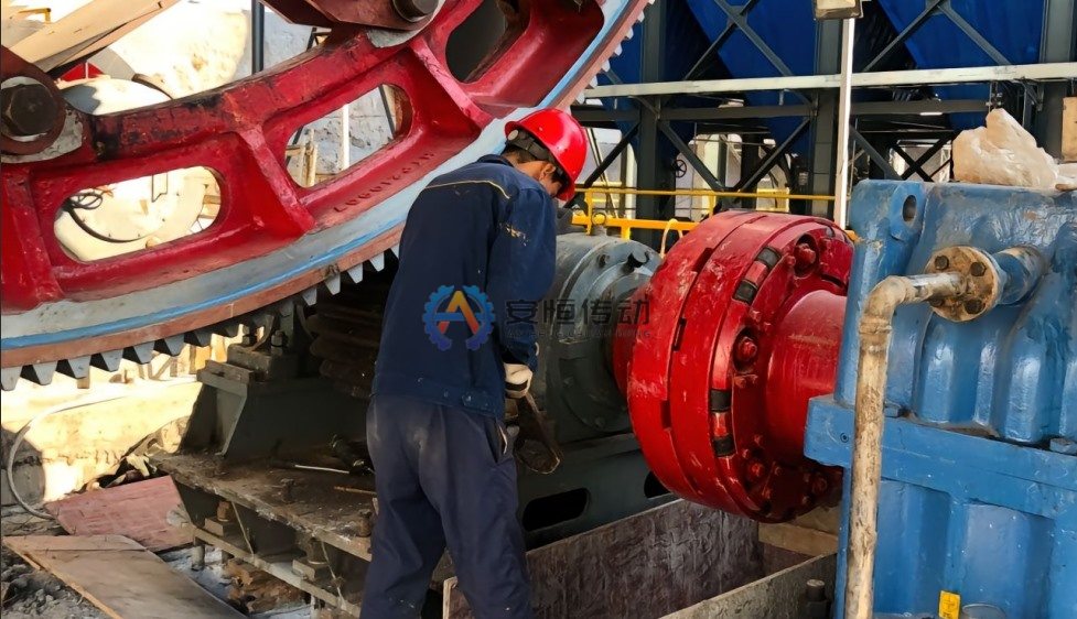
Two coupling positions, two different sets of data
A typical kiln main drive has a coupling between the main motor and the main reducer, and another between the reducer and the pinion shaft. The motor-side coupling runs at motor speed and carries the motor’s rated torque, so bore and keyway on the motor shaft, hub length, shaft end gap and balancing matter most; check also whether a brake wheel is part of it.
The reducer-to-pinion coupling turns slowly but carries the reducer output torque, plus the high breakaway torque needed to start a loaded kiln, and it must accept the angular misalignment that comes with adjusting the pinion against the girth gear. That is why a Drum Gear Coupling is the usual choice there, and why tooth data, bore fit and flange pattern are the critical dimensions. If the auxiliary drive connects through the reducer input shaft or the coupling, record that interface as well.
Plan backwards from the shutdown date
Work back from the day the coupling must be back in service and list what has to happen before that day. The steps you control are data collection and drawing approval; manufacturing time depends on the design and is confirmed after we review the drawing, and transport time depends on your forwarder and route.
- Collect pre-shutdown data, equipment documents and photos, and send the inquiry.
- Agree the drawing and have it signed by both sides.
- Manufacture: standard sizes ship in as little as 10 days and copies made from an old part take from 20 days; non-standard or large sizes are confirmed after drawing review, and urgent orders can be given priority because hobbing, gear shaping, turning, machining and induction hardening are all done in-house.
- Inspection, documents and export packing, then delivery to your freight forwarder’s warehouse in China.
- Transport by your forwarder, by sea freight or by rail freight via Khorgos (China–Kazakhstan border), plus customs and site delivery.
Everything up to and including transport has to be finished before the shutdown starts. If a critical dimension can only be measured after the old coupling is removed, schedule a short stop well before the annual shutdown to measure it, because waiting until the shutdown leaves no time for drawing, manufacturing and shipping.
What you can measure before the kiln stops
Much of the data does not need the coupling off. Take it from equipment documents such as motor data sheets and reducer drawings, which often survive when the coupling drawing does not, and from measurements taken during a brief stop with the drive locked out:
- Shaft extensions on motor, reducer and pinion: visible diameters, lengths and keyway details where documented.
- Gap between shaft ends and between hub faces.
- Installation space: outside diameter clearance to guards and foundations, and axial room to slide the sleeves.
- Flanges and bolt holes: outside diameter, bolt circle, number and size of holes.
- Auxiliary drive interface: type of connection, shaft extension and any overrunning clutch.
Photograph everything with a scale or tape in the picture, and note the nameplate data of motor and reducer. Our old coupling measuring checklist lists the dimensions and photos that make a replacement drawing reliable.
Measuring the old part and correcting for wear
Once the old coupling is off, measure the shafts before the bores. A hub bore that has fretted or worn oversize is not a reference; the new bore should be machined to the measured shaft diameter with the fit the duty needs, and keyway width and depth should be taken from the shaft keyway and the key. Our guide to bore fit and keyway tolerance covers what to confirm.
For a drum gear coupling, count the teeth on hub and sleeve, which must match, and measure the tip diameter of the external teeth and the internal teeth of the sleeve. Take measurements where wear is lowest, at the tooth ends or on the unloaded flank, since copying worn tooth thickness builds the wear into the new part. Note the face width, crowning, lubrication holes and seals too.
If no heat treatment record exists, hardness readings on the old hub and sleeve help choose material and heat treatment. Typical choices are C45 (≈ AISI 1045) or 42CrMo4 (≈ AISI 4140) with quenching and tempering, plus induction hardening of the teeth where the design calls for it.
Before it ships: drawing sign-off, trial assembly and documents
The replacement drawing should be signed by both sides before cutting metal, with bores, keyways, fits, tooth data, flange pattern and overall length all marked as confirmed. If the shafts are measured after the drawing was made, revise and re-sign it rather than passing changes by message.
Agree trial assembly and inspection before the order, for example checking hub and sleeve mesh and backlash in the factory, and gauging bores and keyways against the signed drawing. Documents available with the shipment include a material certificate (mill test certificate), dimensional inspection report, heat treatment report, ultrasonic testing (UT) report and, for the motor-side coupling, a dynamic balancing report. Standard export packing is a black oxide finish with rust-preventive oil, wrapped in plastic film, in an export wooden case.
FAQ
Should we copy the old coupling exactly or choose a standard size?
If the shaft sizes and torque fit a standard series, such as GIICL (GIICL1–GIICL25) with bores from 16 to 1040 mm across the range, a standard size with custom bores is usually quicker and easier to re-order. If the envelope, flange pattern or auxiliary drive interface is unusual, a Custom Replacement Coupling built to the measured old part is the safer route.
Can the bores be finished on site after we measure the shafts?
It is possible with rough-bored hubs and a capable local machine shop, but it adds a risky step inside the shutdown. Measuring the shafts during an earlier short stop and ordering finished bores is almost always better.
What if the old coupling was an imported brand?
The same method applies: shafts, envelope, flange pattern and tooth data define the replacement, not the brand. Send nameplate data if any survives, plus photos and measurements, and we will check whether a standard size or a custom design fits.
Start the replacement before the shutdown is on the calendar: collect what you can measure now, plan backwards from the restart date, and get the drawing signed early. Send us your drawing, or photos and measured dimensions of the old coupling with motor, reducer and pinion data, and we will confirm the design, lead time and documents.
Need an engineering selection or replacement review?
Send power, speed, shaft diameters, keyway, installation dimensions, drawings or old-part photos. We will review the working condition before confirming the model and quotation.